50
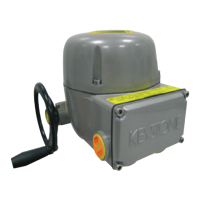
BIFFI ICON 2000
InstructIon and operatIng manual
12.6 THE MANUAL OVERRIDE CANNOT
BE ENGAGED
In case the engagement of the lever is too
difficult, check whether the drive sleeve is stuck
and proceed as follows:
•Openthecover.
•Trytomovethedrivesleevebya
screw-driver.
•Reassemblethecover.
12.7 THE VALVE DOES NOT SEAT CORRECTLY
•Ifthevalveisstoppedbythetorquelimitin
closing, increase the actuator output torque
limit.
•Ifthevalveisstoppedbythepositionlimit
in closing, check that the valve reaches its
seat position, then readjust the setting of the
position limit.
•Theinternaltrimofthevalvemaybe
damaged.
12.8 EXCESSIVE TORQUE FOR VALVE
OPERATION
•Clean,lubricateandcheckthevalvestem.
•Valvepackingtootight:loosenthegland
bolt nuts.
•Couplingtype“A”:tightfitbetweenbushand
stem: increase the thread clearance on the
drive coupling.
•Couplingtypes“B1”,“B2”,“B3”and“B4”:
ensure there are no axial forces on the valve
stem by leaving an adequate axial clearance
between the stem and the drive bush. Also
check that all transmission shafts, universal
joints or bulkhead passages have sufficient
lubrication and check that the transmission
shafts are not bent.
•Checkthattheinternalvalvetrimorthe
reducer gears are well lubricated and not
damaged.
•Checkthealphanumericdisplayfor
diagnostic messages, and proceed with the
suitable corrective actions as described in
this chapter, paragraph 12.11, Diagnostic
messages.
12.9 THE ACTUATOR DOES NOT STOP IN
FULLY OPEN OR FULLY CLOSED POSITION
•Checkthattheactualopenandclose
positions of the valve respectively correspond
to100%and0%ontheactuatordisplay
•Makesurethatthetorqueandtravellimits
are correctly set (see paragraph 9.1, Set-up
routines - Actuator set-up).
12.10 THE NUMERIC POSITION DISPLAY
INDICATES “E01”
•Itisnecessarytore-calibratethestroke
limits (see paragraph 9.1, Set-up routines -
Actuator set-up).
12.5 THE MOTOR RUNS BUT THE ACTUATOR
DOES NOT MOVE THE VALVE
In case the local display does not change the valve
position indicators:
•Checkthatthemanualde-clutchleverisnot
stuck in manual operation position.
•Rotatethehandwheelafewdegreesto
remove all possible sticking between the
handwheel and the drive sleeve.
In case the local display changes the valve
position indicators:
•Verifythestemnutcorrectlyfitsinthe
actuator base.
•Verifythestemnuthassufficientengagement
with the valve stem.
•Verifythekeycorrectlyfitsinbore/keyways
applications.
•Checkthatthevalveworksinmanual
operation. If not, it is necessary to check the
manual control area as follows:
- Loosen the handwheel security dowel.
- Remove the handwheel.
- Remove the cover supporting the
handwheel.
- Check the integrity of the internal parts.
- Proceeding with the assembly, follow the
reverse order of the disassembly.
- Make sure there are no foreign bodies. Pay
attention not to damage the O-ring seals.
 Loading...
