53
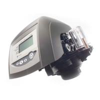
BIFFI ICON 2000
InstructIon and operatIng manual
13. PARTS LIST AND
DRAWINGS
13.1 INTRODUCTION
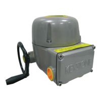
This chapter includes the drawings and parts
list of each component and subassembly of
ICON 2000 actuators.
IMPORTANT
- When ordering spare parts, please indicate
the serial number embossed on the actuator
nameplate.
- When ordering spare parts, please refer to the
item number on the attached drawings.
Configuration obj n°
N° indicates the number of the parameter to
be configured. To clear the alarm the table of
all ICON 2000 parameters is necessary. Call
Biffi After-sales service to solve the problem.
If the alarm message is “CONFIGURATION OBJ
9999” only one of the ICON 2000 parameters
needs to be changed. For instance: enter
the SET-UP menu, actuator set-up, torque
set-up, and either increase or decrease the
closingtorqueby1%.Asthealarmmessage
disappears re-enter the SET-UP menu,
actuator set-up, torque set-up, and set the
previous value (see paragraph 9.1, Actuator
set-up, Torque set-up).
Hardware n°
N° indicates the module that is not working.
The problem may be due to a malfunction of
the module, to an incorrect wiring between
modules, or to an incorrect setting of the
ICON 2000. Call Biffi After-sales service to solve
the problem. The following hardware alarms
can be detected:
- Hardware 1 = incorrect coding of local
push-buttons and selector.
- Hardware 2 = incorrect configuration of
Ain/Aout optional module
- Hardware 3 = no communication between
Ain/Aout optional module and base card
- Hardware 4 = incorrect configuration of type
of terminal board
- Hardware 5 = no communication between
terminal board and base card
- Hardware 6 = incorrect configuration
ICON 2000 / F01-2000
- Hardware 7 = incorrect configuration of type
of bus card
- Hardware 8 = no communication between bus
card and base card
WARNING TABLE
Display message Condition for warning Action
Available controls
WarningLocal Remote ESD
High torque in OP
(near max.)
Measuredtorque10%lowerthanthe
relevant value configured in torque
set-up or stroke limits routines
Check the torque necessary to
move the valve
Available Available Available Close control
High torque in CL
(near max.)
Measuredtorque10%lowerthanthe
relevant value configured in torque
set-up or stroke limits routines
Check the torque necessary to
move the valve
Available Available Available Open control
Internal temp
(near limits)
Temperature inside the actuator
enclosure higher than 80°C or lower
than -35°C
Find the heat source and insulate
the actuator
Available Available Available Control
temperature
>-35°C and <80°C
Main voltage
(near limits)
Value of the main voltage out of the
correctrange(-15%or+10%ofthe
value stated in the name plate menu)
or wrong frequency
Check section of wires and values
of voltage and frequency
Available Available Available Main voltage
correct
(Max.) contactor
cycles
Max. number of contactor cycles
reached
Change contactor and reset
operation log
Available Available Available Clear recent
data log
Maintenance request Date of the next maintenance reached Perform maintenance and set next
maintenance date
Available Available Available Change date
Motor current Motor current greater or lower than
limits
Check electrical motor Available Available Available CurrentOK
Wrong stroke limits The routine that monitors the stroke
limits detects a wrong end of travel
condition
Re-calibrate both stroke limits Available Available Available Re-calibrate both
stroke limits
Bus Fieldbus not working Check bus communication Available Available Available BusOK
 Loading...