4
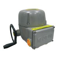
BIFFI ICON 2000 / ICON 2000 AD
Addendum B to InstructIon And operAtIng mAnuAl
7.2.3 Base actuator with extensions [B] or [C]
on the terminal board compartment
The extensions [B] or [C] provide up to
9 additional entries for cable or conduit
connection. With reference to the attached
picture, the thread form/size for the entries is
as follows:
Entries from A to K
Entries
Option 1
Standard
entries
Option 2
Alternative entries
(ISO 965)
A, B, C, D, E, F,
G, H, K
½” NPT M20x1.5
IMPORTANT
When alternative entries are used, indication
of the dimensions is imprinted directly on the
housing close to the entry.
WARNING
Unused entries may remain unmachined or must
be plugged with a certified plug suitable for the
area.
7.3 WIRING
The external wires or the connections of the
external ATEX certified apparatus through
the conduit entry of the additional extension,
must be wired to the internal cards of the
ICON 2000 / ICON 2000 AD in accordance to the
wiring diagram and to the general instructions
attached to the documentation of the base unit.
7.4 CABLE CONNECTION
When optional extension for additional entry/
entries or additional electronic card are used to
connect external cables or conduits, the sealing
of cables/conduits entries must be carried out
in accordance with national standards or the
regulatory authorities that have certified the
extension with additional conduit entry.
Method of sealing and cable glands must be
approved and separately certified for use in
hazardous areas.
Two earth points of connection, one internal
and one external, are foreseen on the base
ICON 2000 / ICON 2000 AD units enclosure for
the ground cables connection.
Internal earth stud
External earth stud
IMPORTANT
To prevent any water infiltration through the line
cable conduits, be sure the cable glands used
have the minimum degree of protection required
by the plant.
To guarantee that the weatherproof and
explosion-proof characteristics are respected,
screw the cable gland or the external ATEX
certified apparatus tightly (at least 5 turns) and
block them with a thread sealant.
IMPORTANT
The cables and cable glands MUST be selected
considering the maximum temperature of the
cable indicated on the label fixed to the base
ICON 2000 unit.
7.5 INSTALLATION IN AMBIENT WITH
EXPLOSIVE DUSTS
Special attention must do to these following
points:
•Beforetheassemblythejointsurfacesmust
be greased with Aeroshell grease.
•Thecableglandsmusthaveaprotection
degree at minimum IP66 or IP68
(15 m depth / 90 hours) according to
IEC/EN 60529 standard.
•Periodicallyverifythequantityofdust
deposited on the enclosure and clean it in the
case the quantity becoming more than 5 mm.
 Loading...
