76570EM 38
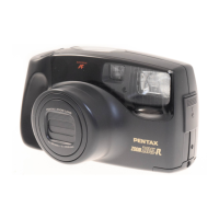
(3) [CONF] The photo sensor must be positioned at the center of
AF frame as shown in the figure below.
(4) [ADJ] Loosen the screw, and then adjust the position of sensor. Tighten screw and ensure
position is not changed. If required, repeat adjustment procedures.
(5) After adjustment is completed, apply the screw lock agent or Super-X to 0-J100 (2 places) as
shown in the figure above right.
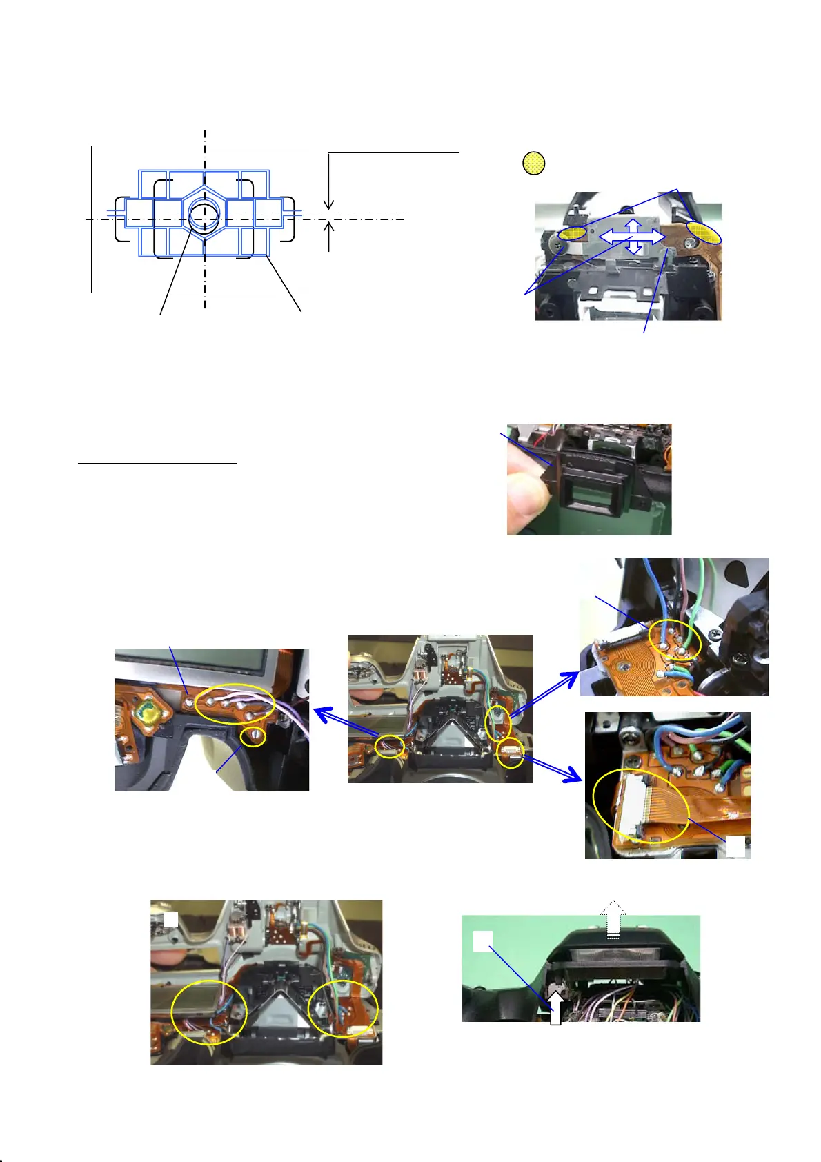
19. 0-A301 Top cover
Confirm the instillation of parts before installing 0-A301.
(1) Confirm that soldering on the main SW land
is not connected
(2) Install M311
(3) Put 0-A301 on the main body.
(4) Solder 4 lead wires (Blue, Green, Black, and Brown)
(5) Put flex board into the connector
(6) Solder 4 lead wires ( Pink, Purple, Black, Brown)
(7) Pop-up flash
(8) Arrange lead wires and put top cover to the body
: Bonding position
AF frame for spot metering (φ2.5)
Tolerance: 0.0~1.0mm
Center position of sensor
Center position of Viewfinder
Photo sensor (0-J100)
J100
⑤
④
④
⑥
⑤
①
⑦

 Loading...