UC***-18GS series
Installation
2020-11
15
3.4 Connection
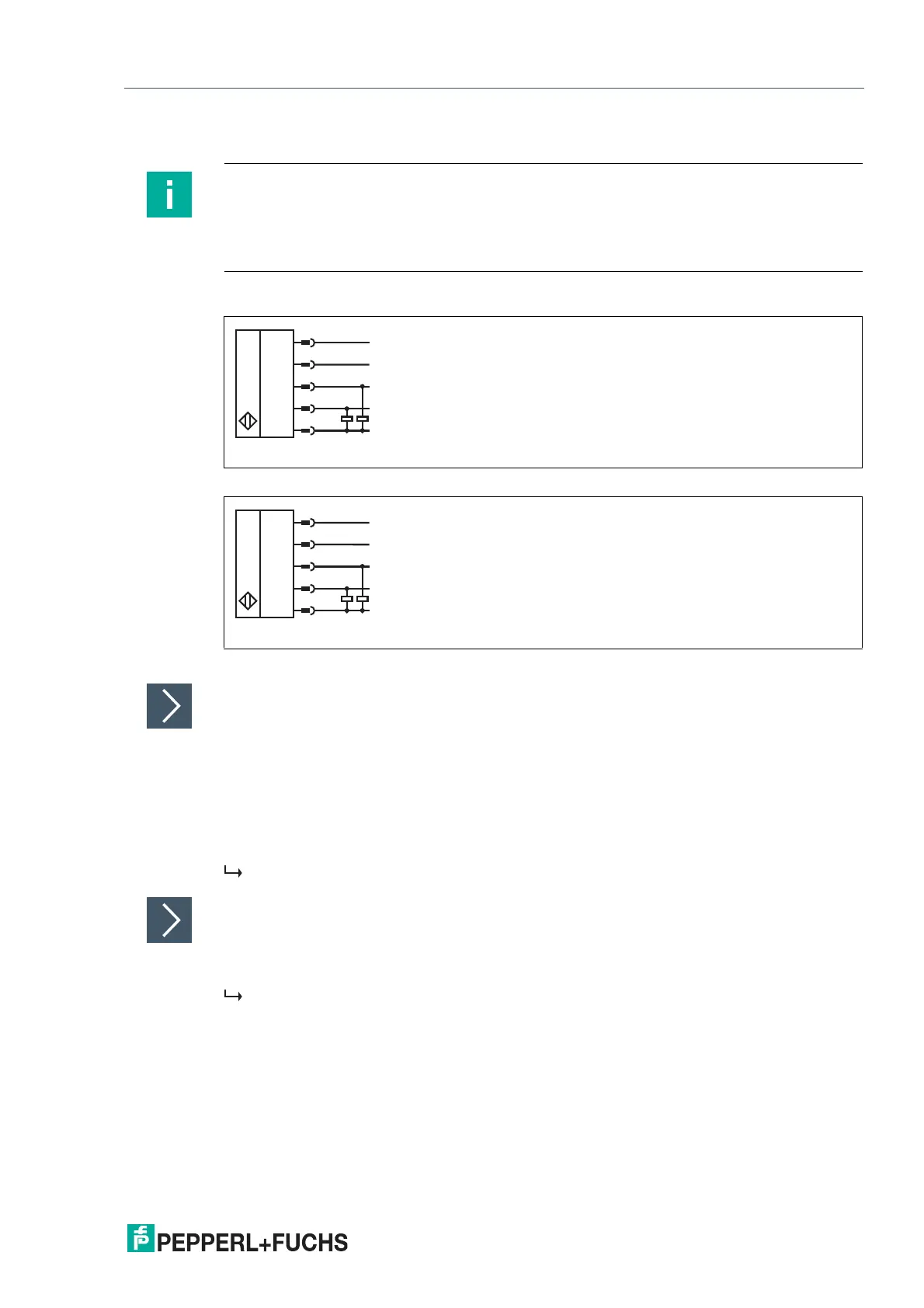
Connection Images
Figure 3.2 UC****-18GS-2EP-IO-V15
Figure 3.3 UC****-18GS-IUEP-IO-V15
Applying Supply Voltage for a Sensor with Connector Plug
To supply voltage to the sensor, proceed as follows:
1.
Insert the prepared connection cable into the connector plug provided for this purpose on the
underside of the housing.
2.
Screw the union nut onto the connector plug as far as it will go. This ensures that the power
cable cannot be pulled out inadvertently.
3.
Connect the supply voltage to the cables provided for this purpose and switch it on.
The sensor is ready for operation.
Control via IO-Link
To prepare the sensor for control via IO-Link, proceed as follows:
Connect the sensor to an IO-Link master. For a sensor with connector plug, screw the union nut
onto the connector plug as far as it will go. Use a four-strand sensor cable for the connection.
The sensor is now prepared for IO-Link communication.
Note
A three-pin adapter or triple-strand connection cable must be used when connecting the
sensor to an IO-Link Class B master port.
If the synchronization option is unused, connect the synchronization input to ground (0 V)
during operation without IO-Link.