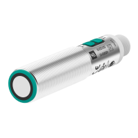
UC***-18GS series
Description of Sensor Parameters
2020-11
47
Figure 8.4 Example of behavior of a "normally-open" push-pull / PNP switching output in
retroreflective mode
Deactivated
The switching output will stop changing if it is deactivated. It will remain in the most recent state
before deactivation.
The switch state can be changed manually using the "Output logic" parameter. This function is
useful when you want to manually trigger a switching signal with a longer pause, to test that the
sensor or the machine is working correctly.
8.2.2 Output Logic
You can use this parameter to set the logic of the switching output.
8.2.3 Switch Point 1
You can use this parameter to adjust the switch point 1 in "mm", measured from the ultrasonic
transducer surface of the sensor.
If switch point 1 is set to a farther distance than switch point 2, the two switch points are virtually
inverted within the sensor. This is done to ensure that the set output mode is working as
intended.
Warning!
Risk of sensor damage in the event of improper use!
This function is not intended for recurring deactivation of the sensor in continuous operation;
doing so may damage the electronics.
This function is intended for testing purposes only.
Parameter name Access Value range
Output logic Read/write • Normally-open
• Normally-closed
Table 8.3
Parameter name Access Value range
Switch point 1 Read/write <Beginning of adjustment
range> ... <End of adjustment
range< [mm]
(See technical data in the sen-
sor datasheet)
Table 8.4
Note
The DTM also accepts values between <Beginning of sensing range> and <Beginning of
adjustment range> as well as values above <End of adjustment range> up to a certain limit.
Values in these ranges are outside of the adjustment range specified by Pepperl+Fuchs; use
them at your own risk.

 Loading...