2
1
28
B1 Planning the Supporting Structure
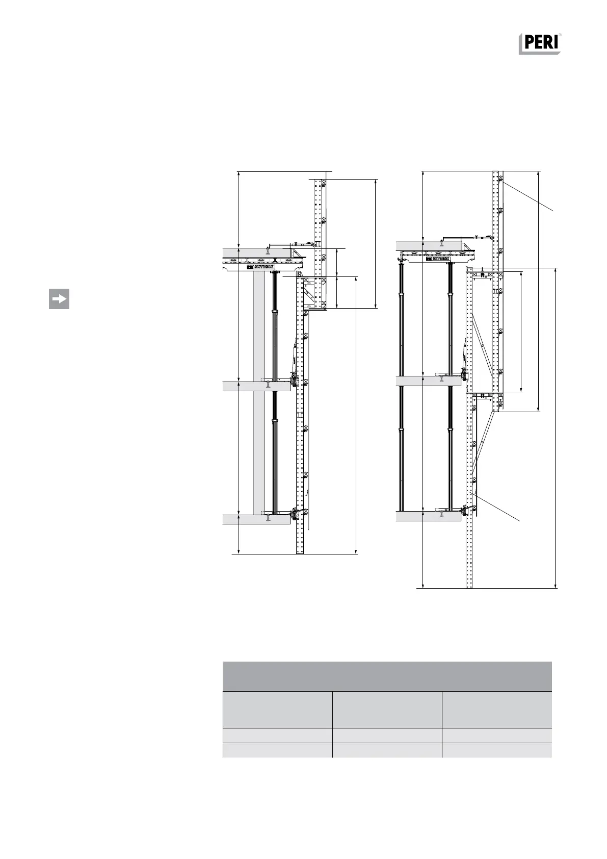
System Dimensions
Climbing Rails
The length of Climbing Rail L1 (2) corre-
sponds to the height of the storeys hB.
It must correspond to at least the
height of two successive storeys plus
an overlap for safety reasons.
With changing storey heights, the
largest dimension of two consecutive
storeys must be selected.
Projecting height of the protection
panel h
P
≥ 2.00.
– At least 2 Slab Shoes must guide
each Climbing Rail at all times.
– It is possible to plan so that the
Climbing Rail does not overlap 2 entire
storeys for those intermediate storeys
with larger storey heights. In this
case, self-climbing is not possible.
When climbing with the crane, spe-
cial measures are required because
there is no guide in place for the
Climbing Rail. These special measures
must be defined in manufacturer-
specific assembly instructions.
Calculation: Version 1
(Fig. B1.01)
Climbing Rail RCS (2)
L
1
≥ h
B1
+ h
B2
+ 28 cm.
Enclosure Post RCS (1)
L
2
≥ h
3
+ h
4
+ hp
Calculation: Version 2
(Fig. B1.02)
Climbing Rail RCS (2)
L
1
≥ h
B1
+ h
B2
+ 28 cm.
Enclosure Post RCS (1)
L
2
≥ h
B2
+ h
p
.
h
B2
h
B2
h
p
h
p
h
2
h
3
h
4
L
1
L
1
L
2
L
2
h
B1
h
B1
≥28
≥28
Fig. B1.02
Fig. B1.01
Version 2Version 1
Climbing Rails depending on
storey height h
B
Climbing Rails
max. storey heights
h
B1
+ h
B2
with a constant storey
height
max. h
B1
= h
B2
7.4 8 m 7.20 m 3.60 m
9.98 m 9.70 m 4.85 m
RCS P Climbing Protection Panel
Instructions for Assembly and Use – Standard Configuration

 Loading...

