TPD1317e Chapter 2
Page 9
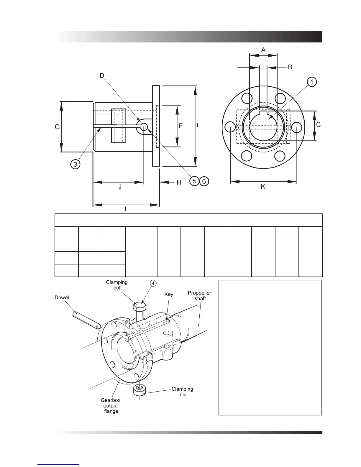
Dimensions in inches
A B C D E F G H I J K
1.25 0.31 1.39
Drill 15/32
Ream
0.5005-0
5.75 3.0 3.4 1.12 4.25 3.12 4.761.38 0.31 1.52
1.50 0.38 1.67
Machining Procedure
Bore to size (dimension ‘A’).
Broach keyway 4.0” long (dimension
‘B’).
Split, 0.135 Max. width (dimension
‘J’).
Clamp the coupling to the propeller
shaft in the position shown.
Drill 15/32” Diameter hole through
the propeller shaft and far side of
the coupling, using the starter hole
(dimension ‘D’).
0.5005-0.4990 Diameter ream
through both the coupling and shaft.
Dismantle and clean, then assemble.
1.
2.
3.
4.
5.
6.
7.
Figure 3 - Twin Disc gearbox couplings
 Loading...

