TPD1317e Chapter 7
Page 43
7.2 Fuseboard
Note: Fuses are provided to protect the electrical system against accidental short circuits. The risk is highest
when the engine is being installed, or when additional equipment is wired in, and is negligible during normal
operation.
On all models the fuseboard may be found behind a plastic cover, adjacent to the starter motor.
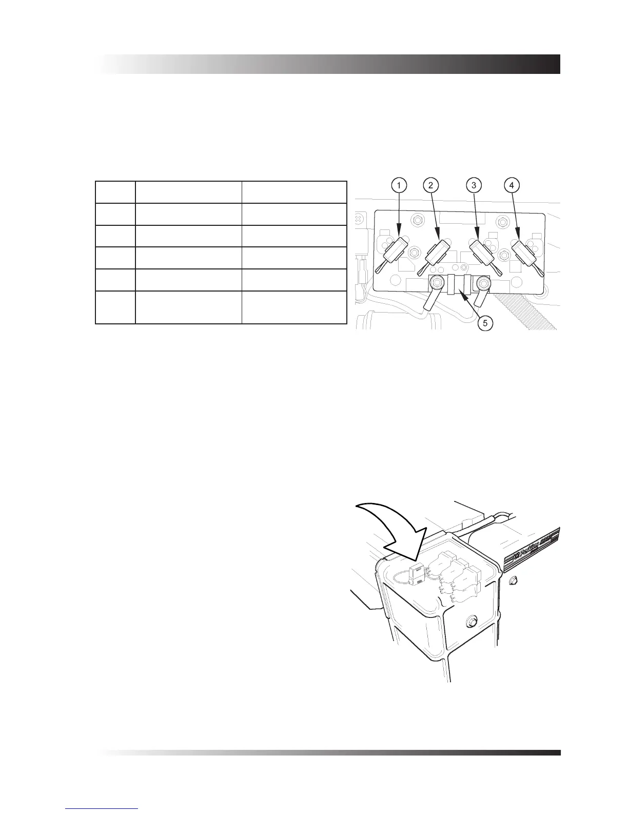
For identication of fuses. (See Figure 8).
Negative fuse - 6 cylinder models only
An additional fuse is located at the front of the engine, behind the plastic belt cover (see Figure 9). This fuse is
to protect the engine wiring from damage due to the cylinder block being inadvertently connected to the battery
positive, and then grounded through the earth relay.
Note: When replacing the -ve fuse, the earth relay must also be replaced.
Fuse 4 cylinder models 6 cylinder models
1 Start 40A Start 40A
2 Not tted Heat 25A
3 Panel 10A Stop 25A
4 Negative 25A Panel 10A
5
Fast fuse - 80A nom.
Check value of fuse.
-
Figure 8 - Fuses
Figure 9 - Negative fuse
 Loading...

