TPD1317e Chapter 3
Page 13
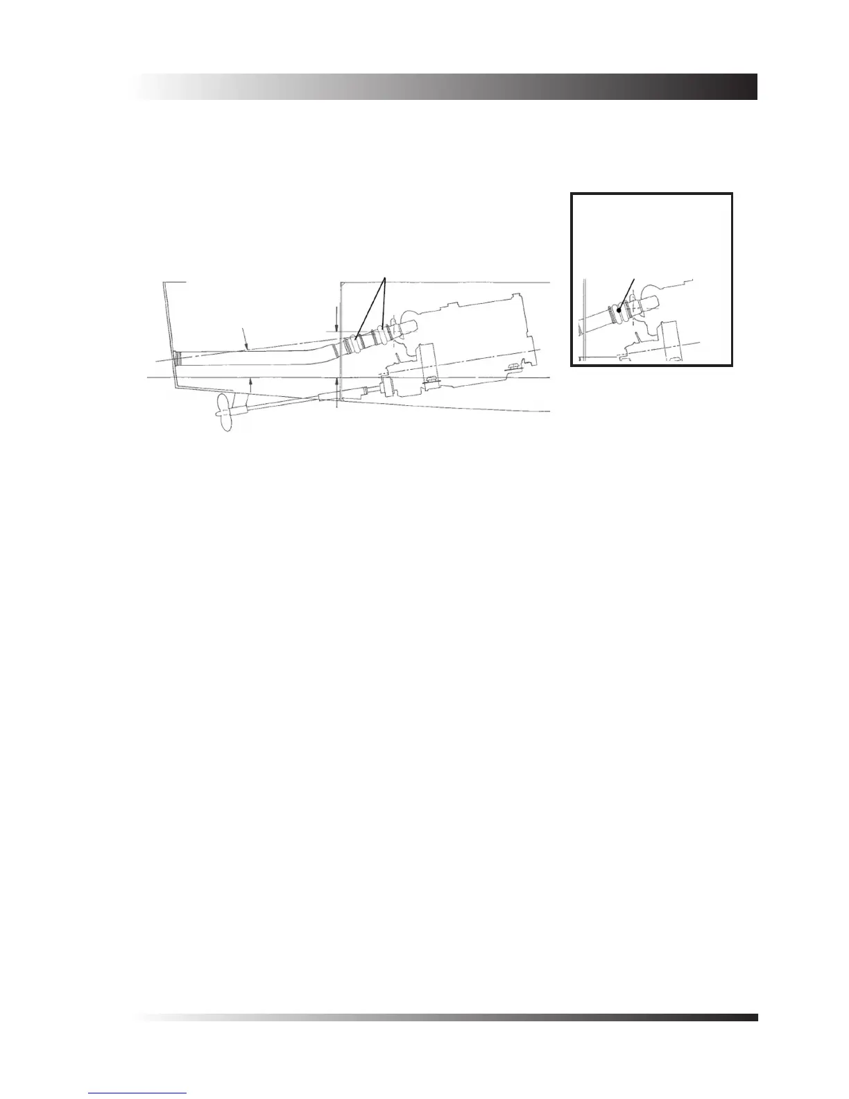
Due consideration must be given to providing exibility in the exhaust hose, particularly if the engine is exibly
mounted. Where the exhaust hose must pass through a bulkhead immediately behind the engine it is preferable
that the arrangement shown in Figure 3 is adopted, using rubber bellows to provide exibility. Note that the
bellows should be in an unstrained condition when tted.
3.2 Dry Systems
Dry exhaust systems for marine installations need careful design to minimize the disadvantages of enclosing
components that are at a high temperature in conned spaces.
The rst part of a dry system should include a exible connection so that excessive weight is not carried by the
connection to the engine. Connections of the stainless steel bellows type are suitable, but care must be taken
to ensure that they are only required to accommodate movements that do not involve twisting the ends of the
bellows relative to each other.
The remainder of the exhaust system should be well insulated to avoid re risk.
If there is a long exhaust run which gains height as it leaves the engine, it may be necessary to incorporate a
trap to collect condensate and allow it to be drained.
Figures 4, 5 , 6, 7 & 8 show typical systems. The minimum bore of the exhaust pipe should be 76mm (3 inches)
for turbocharged engines, 63mm (2.5 inches) for naturally aspirated engines.
Point of water
injection to be
200mm (8 inches)
minimum height
above water line
5
o
minimum average fall
For turbocharged 6 cylinder
engines use silicone rubber
bellows
For turbocharged 6
cylinder engines, use
a single double hump
bellows where space is
restricted.
Figure 3 - Movement of the engine on the exible mounts must not be restricted by
the exhaust hose. Use rubber bellows as shown where space is restricted.
 Loading...

