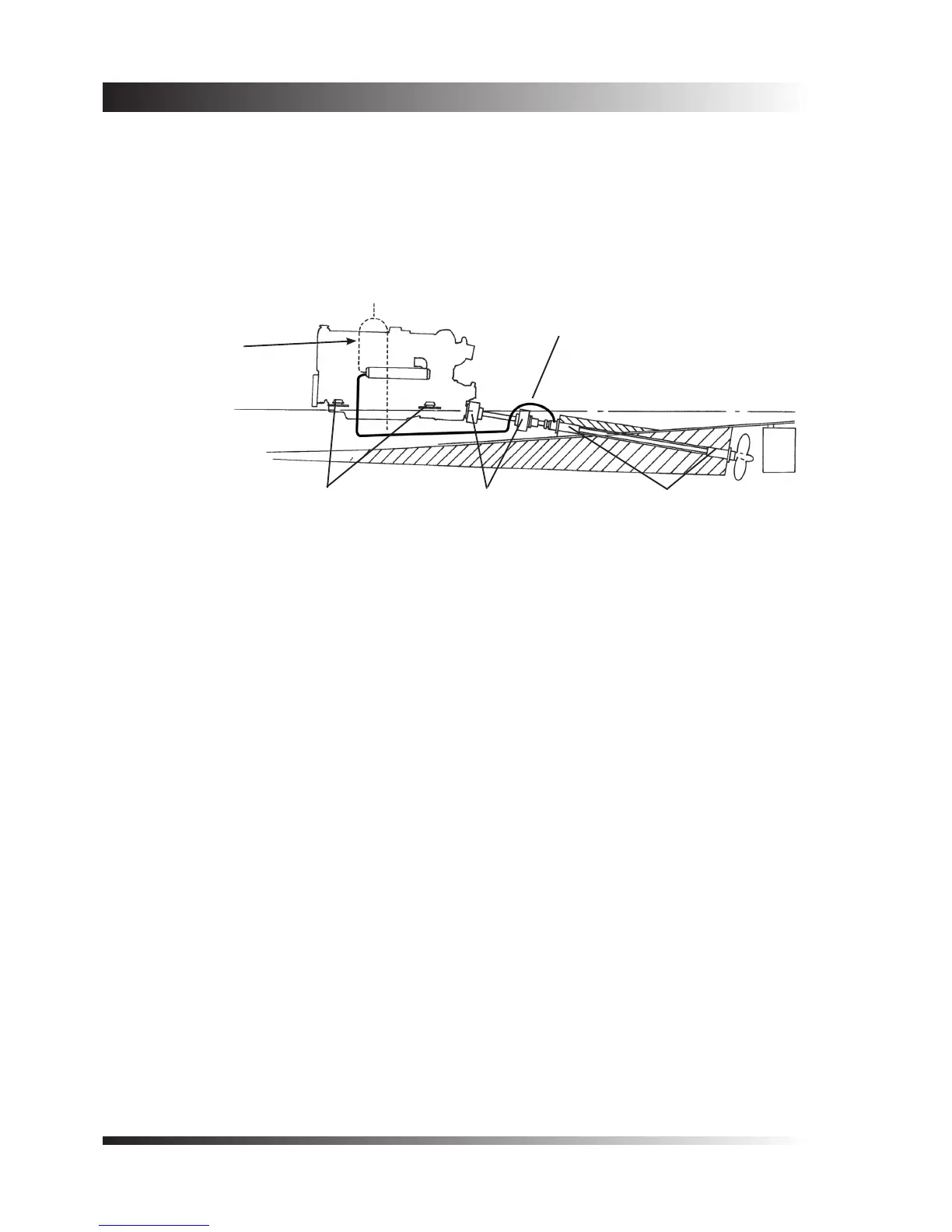
Where the propeller shaft length is such that it cannot be simply supported by the gearbox coupling and ‘P’
bracket, without the risk of whirling, the arrangement shown in gure 2 may be adopted.
In this case one or more additional bearings are included in the shaft log, and exible shaft couplings (which
will accept thrust) are used to permit the engine to move on the exible mountings.
A variation of this system is to use a thrust block (bearing) at the point where the shaft emerges from the log
into the engine room, together with constant velocity joints at each end of the short shaft connected to the
gearbox coupling.
2.2 Gearbox Output Couplings
Flanged propeller shaft couplings, to suit the gearbox output couplings offered by the many gearbox
manufacturers, come in a number of different shapes and sizes, and a variety of methods can be employed to
grip the propeller shaft.
A traditional and sound method is to provide the same taper at both ends of the propeller shaft, so that the
gearbox coupling can be machined at the same time as the propeller. This system is still commonly employed,
particularly where high thrusts and heavy boats are involved. If the shaft becomes worn it can be turned end
for end, and re-used at minimum cost.
As an alternative to the above procedure the method shown in gure 3 may be adopted. Flanged couplings
supplied with Twin Disc gearboxes are intended for this system. The shaft is gripped by means of a split
coupling, with a key to provide positive drive, and a dowel pin to eliminate the possibility of the shaft being
drawn out of the coupling when going astern.
For lighter duty applications the system shown on gure 4 may be employed, utilising the anged couplings
supplied with Hurth gearboxes. In this case ahead thrust is taken directly by the gearbox output shaft, as the
propeller shaft is butted against it. The shaft is secured by means of two half dog setscrews which also prevent
loss of the shaft when going astern. Positive drive is provided by a key.
Water supply for bearings (use hose from 1/4” BSP
tapping on heat exchanger end cap). End cap with
tapping is optional.
Flexible mountings
Flexible shaft couplings Shaft bearings
Warning! Use a
syphon break where
a water lift exhaust
system is specied.
See section 3.4
Figure 2 - Alternative shaft arrangement
 Loading...

