Figure 5 - Typical engine mounting brackets - refer to installation
drawings for specic applications.
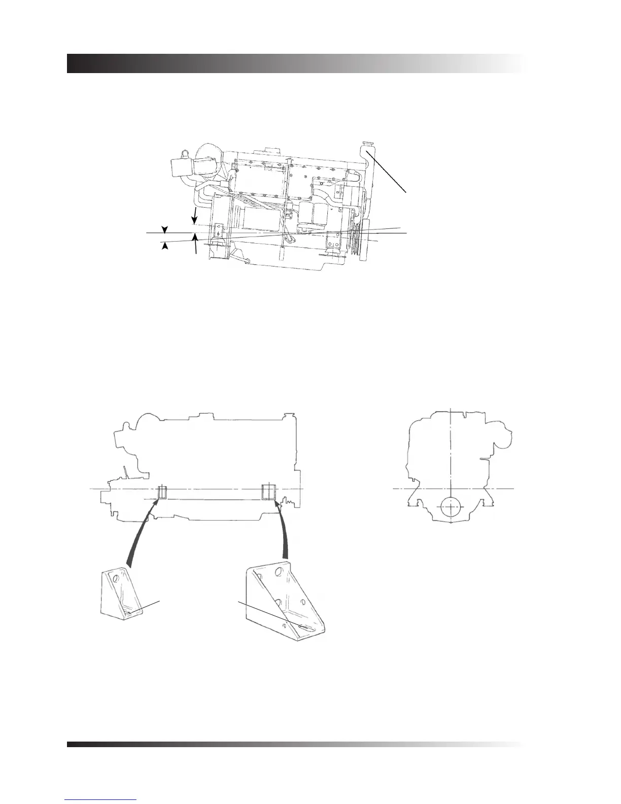
Slotted hole 36 x 17
(1.7/16” x 21/32”)
allows sideways engine
movement
(c) A kit of parts is available to modify 6 cylinder models (only) so that they are suitable for installation with the
ywheel end of the crankshaft above the pulley end by up to 5
o
. An allowance has been made for an additional
3
o
rise to occur in service, when climbing waves or on to the plane.
1.2 Engine Mounting Brackets
The standard brackets, provide mounting points which are 76mm (3 in.) below, and parallel with, the crankshaft
centre line. The brackets may be used to mount the engine directly on the engine bearers, but for all applications
it is recommended that exible engine mounts are used.
The holes for the holding down bolts are slotted, to allow for some movement during the nal stages of
alignment. Where ne alignment is not necessary, for example when a exibly jointed drive shaft is used, the
bolts on all four corners of the engine should be positioned at the end of the slot - all either fully in or fully out.
This will provide additional security in the xing arrangements.
SWL
5
o
Maximum
ywheel up
3
o
ywheel
down
SWL
Header tank
raised using a
special kit of
parts
Figure 4 - Six cylinder models may be installed in a horizontal or nose
down attitude if a special kit of parts is tted, to raise the header
 Loading...

