TPD 1317e Chapter 1
Page 3
Engine Mounting
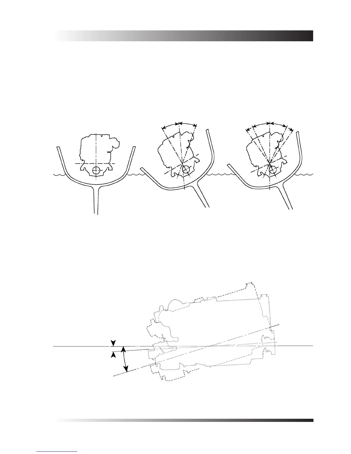
1.1 Installation Angles
(a) The engine is intended to be mounted so that the cylinders are vertical, when viewed from ahead or astern
(gure 1). The heel angles that are permissible in service are shown in gure 2a for 6 cylinder models, and 2b
for 4 cylinder models.
(b) In standard form all engine models are suitable for installation so that in side view the crankshaft is ‘ywheel
down’ from a minimum of 3
o
to a maximum of 17
o
. An allowance has been made for an additional 3
o
rise to
occur in service, when climbing waves or on to the plane.
Figure 1 - Vertical
installation.
Figure 2a - Acceptable
heel angle for 6 cyclinder
models.
Figure 2b - Acceptable heel
angle for 4 cyliinder models.
SWL
3
o
Minimum
17
o
Maximum
SWL
Figure 3 - When in standard form all engine models may be installed ‘ywheel
down’ from a minimum of 3
o
to a maximum of 17
O
.
30
o
Maximum
30
o
Maximum
25
o
Continuous
35
o
Intermittent
 Loading...

