TPD1317e Chapter 7
Page 37
Engine Electrical Systems
A plug-together electrical system is available with the engine, providing the following choices:-
Earth return or insulated return (except M115T, which is earth return only).
Interconnecting cables of 4, 6, 8, 10 or 12m length.
A ‘Y’ harness to allow multiple instrument panels to be tted.
12V or 24V operation.
Instrument panels - basic or comprehensive, which may be used individually or in combination.
7.1 Engine Wiring Looms
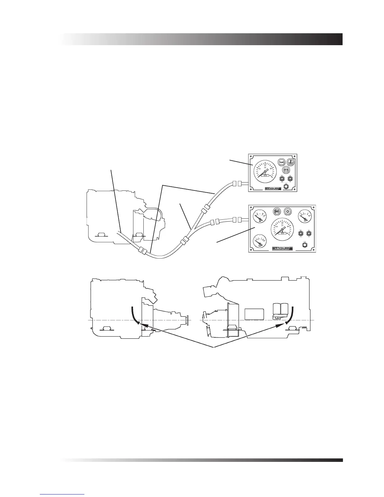
The engine wiring loom connects the starter, alternator, fuse board, electric stop, engine senders and warning
switches to a waterproof (IP67) multiway connector situated on a ying lead attached to the engine at the
positions shown on Figure 2.
The circuit diagrams for the various models are listed below:-
Figure 3 All 4 cylinder models - earth return.
Figure 4 M92 - insulated return.
Figure 5 M92B - 12 and 24 volt insulated earth.
Figure 6 All 6 cylinder - insulated and earth return.
Figure 7 6 cylinder - insulated and earth return, tted with Motorpal PP6M 10Pi fuel injection pump.
•
•
•
•
•
Control panel
Interconnecting
lead
‘Y’ harness
Instrument panel
Connection to
engine loom
Figure 1 - Elements of the plug together system.
Figure 2 - Position of the multi-way connector for the engine wiring loom.
4 cylinder 6 cylinder
 Loading...

