TPD1317e Chapter 5
Page 29
À
Á
À
Á
à
à
à
à
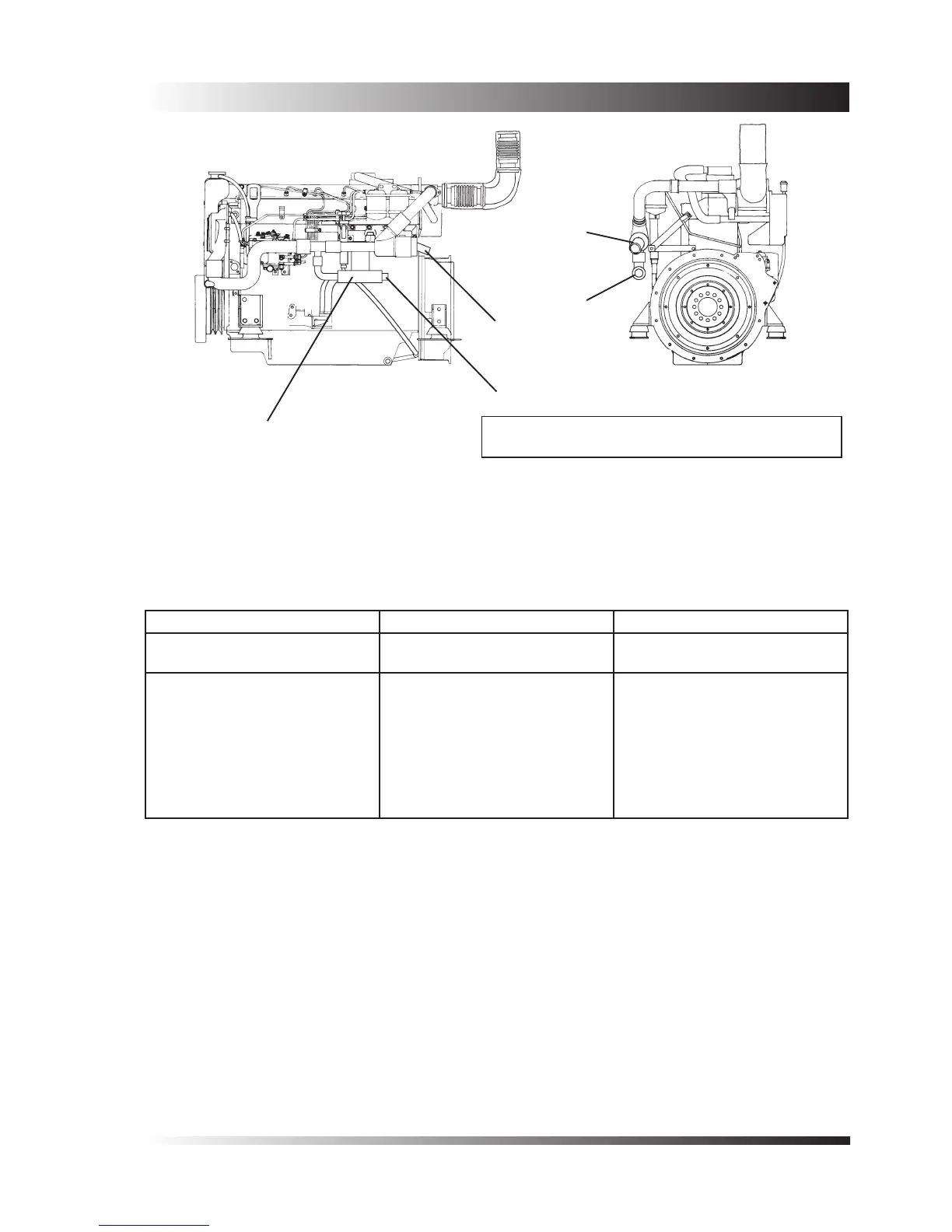
Optional Gearbox
Oil Cooler
À Engine circuit inlet for 45mm (1.75”) diameter hose
Á Engine circuit outlet for 45mm (1.75”) diameter hose
Figure 3 - Connections for keel coolers (M130C, M135)
5.5 Keel Cooling System: M115T M92 and M92B engine
Both engine models may be purchased in a form suitable for keel cooling. Figure 4 shows the connections
provided for the keel cooler.
M115T M92 / M92B
Engine circuit
Heat rejection
74kW (4200Btu/min) 60kW (3400Btu/min)
Design value for the water tem-
perature at the exit from the keel
cooler.
Design value for the water ow
through the cooler.
Pipework to suit 45mm (1.75”)
bore hose connections.
60
o
C (140
o
F)
45-70 l/min
(10-15 galls/min)
60
o
C (140
o
F)
45-70 l/min
(10-15 galls/min)
The pipework between the engine and the cooler should be as short and direct as possible but should be
sufciently exible to allow the engine to move on it’s exible mountings. The layout should discourage the
formation of air locks, and venting points should be provided wherever an air lock is likely to occur.
The keel cooling system should normally be lled with a water/antifreeze mixture containing 50% antifreeze.
This mixture is necessary even in warm climates, as the antifreeze contains corrosion inhibitors which protect
the engine cooling system.
 Loading...

