Chapter 1 TPD 1317e
Page 6
1.4 Engine Bearers
The materials and methods of construction of engine bearers which have proved to be satisfactory in service
vary to such an extent that it is difcult to lay down universal guide lines. However, as a rough guide it can be
said the engine bearers should be capable of supporting a static load of about eight times the weight of the
engine, to cater for the effects of rough seas.
The bearers should be cross connected to give lateral rigidity, in order to maintain the shaft alignment and to
prevent twisting and racking forces being applied to the engine.
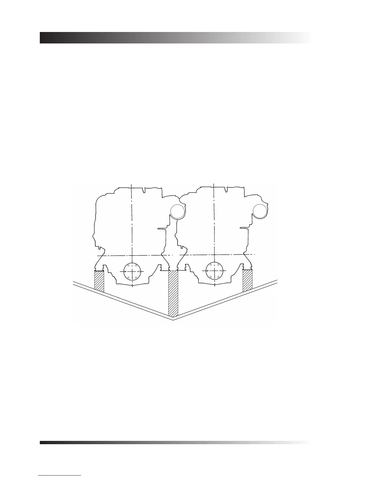
To enable minimum shaft centre distances to be achieved in a twin installation, a common centre bearer
supporting the inner mountings of both engines is sometimes used as shown in gure 7. By this method shaft
centres down to 690mm (27”) may be adopted, but wider spacing is desirable.
The shaft centres could be theoretically reduced further, but this would result in the engine accessibility
becoming very restricted, and it would be impossible to carry out service operations. It should be noted that
if minimum shaft centres are to be adopted, space must be left in front of and behind the engine to provide
access. A minimum clearance on all sides will mean that the engine cannot be serviced!
Figure 7 - Illustration of the closest practicable engine spacing.
With this arrangement access space must be provided ahead and
behind the engines for servicing.
 Loading...

