TPD1317e Chapter 2
Page 7
2.1 Propeller Shafts
It is recommended that all engines are mounted on exible mountings, which will reduce the transmission of
noise and vibration, and will prevent hull movements resulting in forces being applied to the engine.
The responsibility for the design and installation of the transmission system connected to the marine gearbox
lies with the boat designer, the boat builder, the naval architect or the engine installer. It is recommended that
a Torsional Vibration Analysis (TVA) is carried out on the complete drive system. Mass Elastic Data on the
engine can be provided on request from Sabre Engines Ltd. The following observations are offered, to show
some of the systems currently in use.
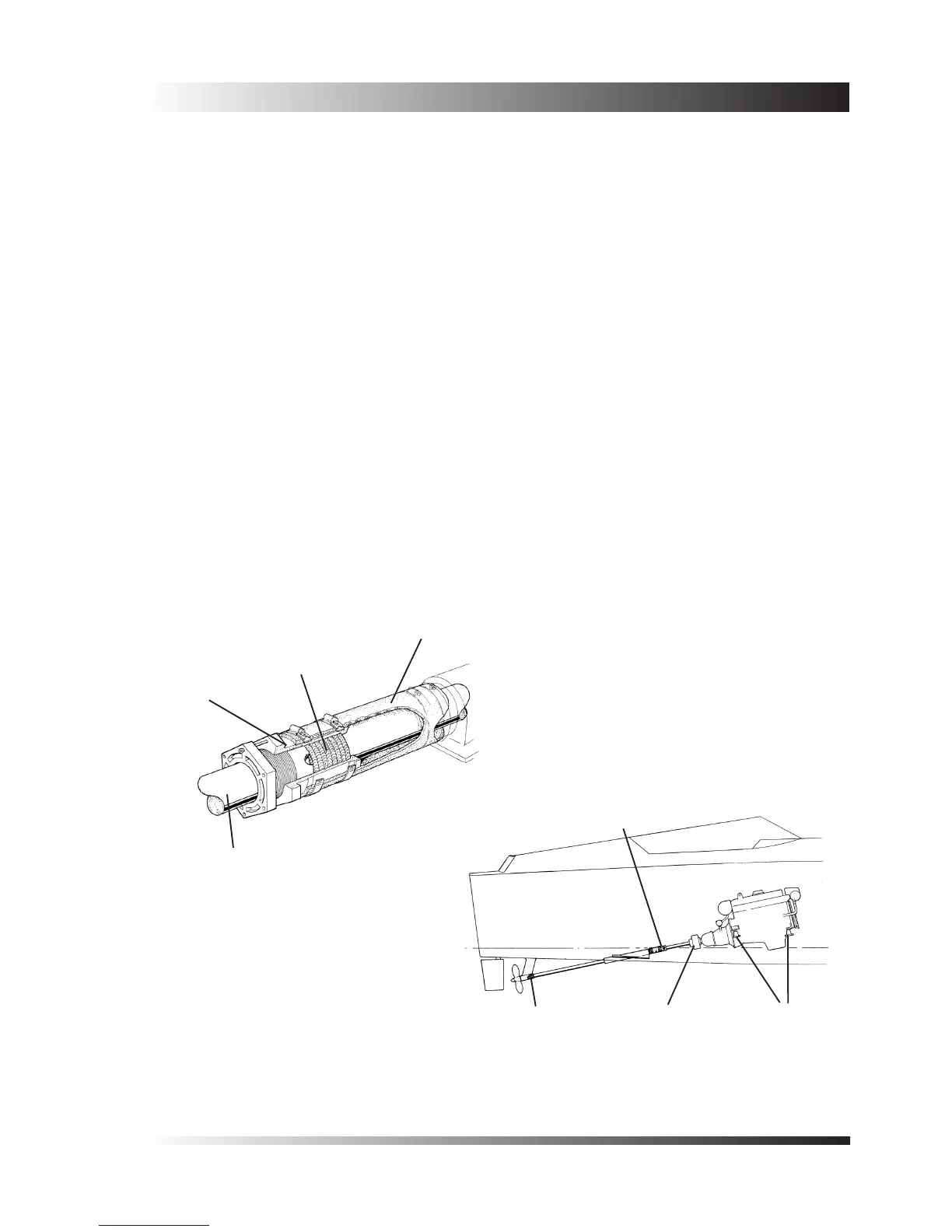
Figure 1 shows a simple arrangement, where the propeller shaft is supported only by the gearbox coupling
and an outboard rubber bearing at the propeller end. Entry of water into the boat is prevented by a shaft seal,
which must be exibly mounted to allow for engine movement. A exible shaft coupling is tted to the gearbox
coupling, to allow momentary angular misalignment in operation.
This system is only suitable for applications where the speed, diameter, and unsupported length of the propeller
shaft will not induce ‘whirling’ (i.e. the centrifugal force generated by the speed of rotation is not sufcient to
bend the shaft into a bow shape).
Propeller Shafts and Couplings
å
Flexibly mounted
shaft seals
Cutless
bearing
Flexible shaft
coupling
Flexible
mountings
Reinforced
rubber hose
Graphited asbestos
string
Stufng
box
Shaft
 Loading...

