Adjustment
13 - 7
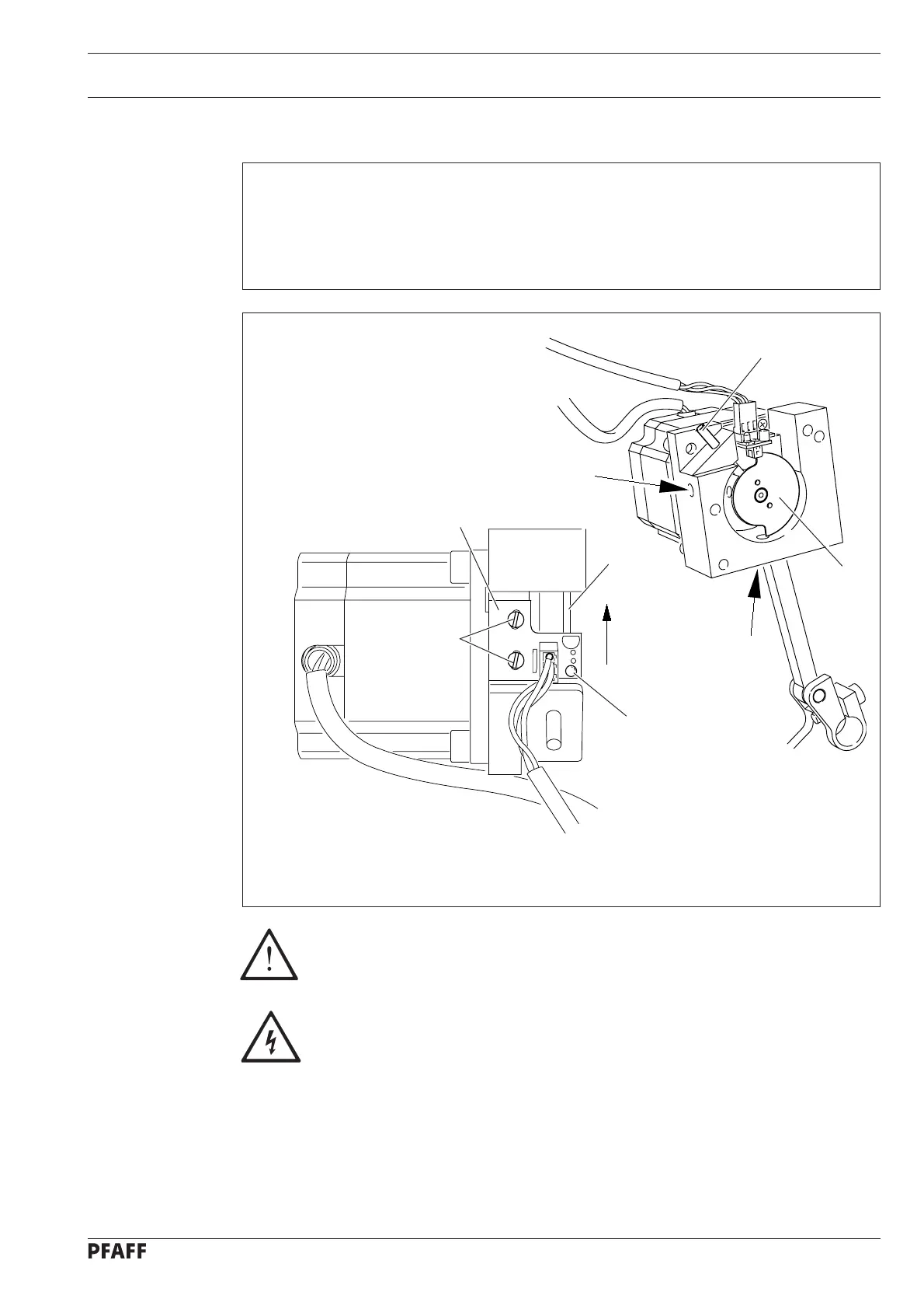
To change the sensor board, it is imperative to observe the following work
steps!
Electric voltage!
Danger of an electric shock if handled incorrectly!
● Completely remove the needle drive unit (plugs remain connected).
● Loosen screws 2.
● Lock eccentric 1 by placing the locking pin 3 (part no. 13-030 272-05) in the locking hole of
the mounting bracket.
Fig. 13 - 06
1
2
2
3
5
4
6
1
13.09 Sensor board of the needle drive (in dismantled condition)
Requirement
1. When parameter "610" is set at "1", the recess in eccentric 1 should match the locking
hole in the mounting bracket.
2. The switch lug of eccentric 1 should be axially centred to the hybrid light barrier of the
sensor board.

 Loading...


