Adjustment
13 - 9
64-104
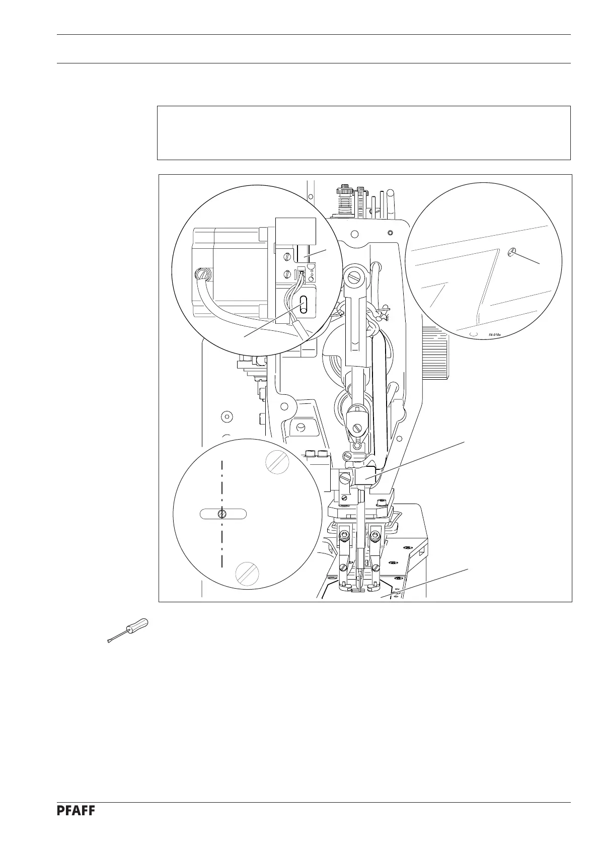
Fig. 13 - 07
4
5
64-077
2
3
1
13.10 Basic setting of the needle drive
Requirement
With the needle bar at its b.d.c. and with eccentric 2 locked, in the crosswise direction of
the arm the needle should be in the centre of the needle hole.
● Switch on the machine and set parameter "610" at "1".
● Unscrew cloth plate 1.
● Using the balance wheel, set the needle bar at its b.d.c. and lock eccentric 2
(locking pin 3, part no. 13-030 272-05).
● Adjust the needle bar frame 4 (screw 5) in accordance with the requirement.
● Remove locking pin 3.

 Loading...


