Adjustment
13 - 11
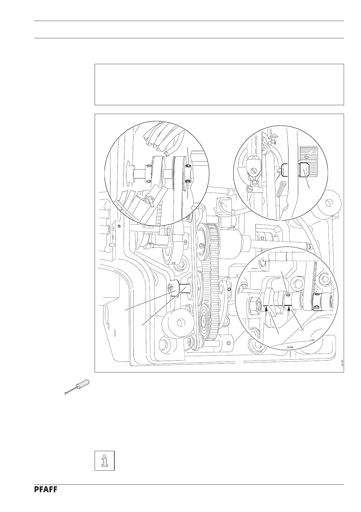
Fig. 13 - 09
3
7
64-078
2
64-108
1
1
6
4
5
13.12 Adjusting the drag link mechanism
Requirement
When the needle bar is at t.d.c.
1. The milled slot in shaft 3 should be in alignment with the milled slot of the cast iron bracket 7.
2. The milled slot of crank 4 should be in alignment with the front edge of driving crank 6.
● Loosen screw 1 on the arm shaft.
● Using the balance wheel, set the needle bar at t.d.c. and lock it with locking pin 2.
● Adjust shaft 3 in accordance with requirement 1 with the aid of the needle rise gauge
(2.4 mm).
● Tighten screws 1.
● Turn crank 4 (screws 5) in accordance with requirement 2.
● Remove locking pin 1.
If the position described in requirement 2 is not reached, driving crank 6 must
be installed accordingly.

 Loading...


