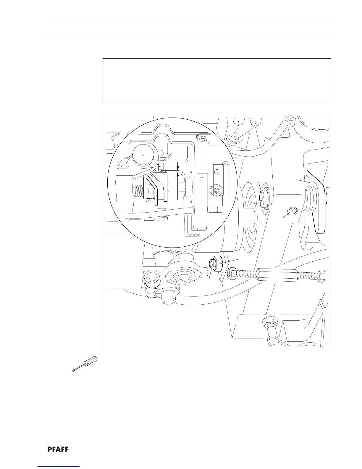
Adjustment
13.05.02 Roller lever
Requirements
1. With the roller lever 6 in resting position and the needle bar at TDC, there must be a
clearance of 0.3 mm between roller 7 and control cam 8.
2. When the thread trimmer is on and the needle bar is at BDC, roller 7 must be in the
middle of the recess in control cam 8.
● Position the needle bar at TDC.
● Bring the thread trimmer to resting position.
● Move eccentric 1 (screw 2) in accordance with requirement 1.
● Position the needle bar at BDC and disengage latch 3.
● Turn screw 4 (nut 5) in accordance with requirement 2.
Fig. 13 - 20
6
7
8
0.3 mm
1
2
3
4
5
13 - 24