Mechanical Instructions
EN 10 BJ2.4U/BJ2.5U LA4.
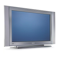
4.3.4 Side I/O Panel
1. Remove the rear cover, as described previously.
2. Release clamp [1] and slide the PWB out of its casing.
3. Unplug connector [2] from the panel.
Figure 4-7 Side I/O Panel 1/2
Figure 4-8 Side I/O Panel 2/2
4.3.5 Memory Card reader / USB connector
1. Remove the rear cover, as described previously.
2. Release clamps [1] and slide the unit out of its plastic
frame.
3. Unplug the USB connector from the SSB panel, and the
power cable from the platform PSU.
Figure 4-9 Memory Card reader / USB connector
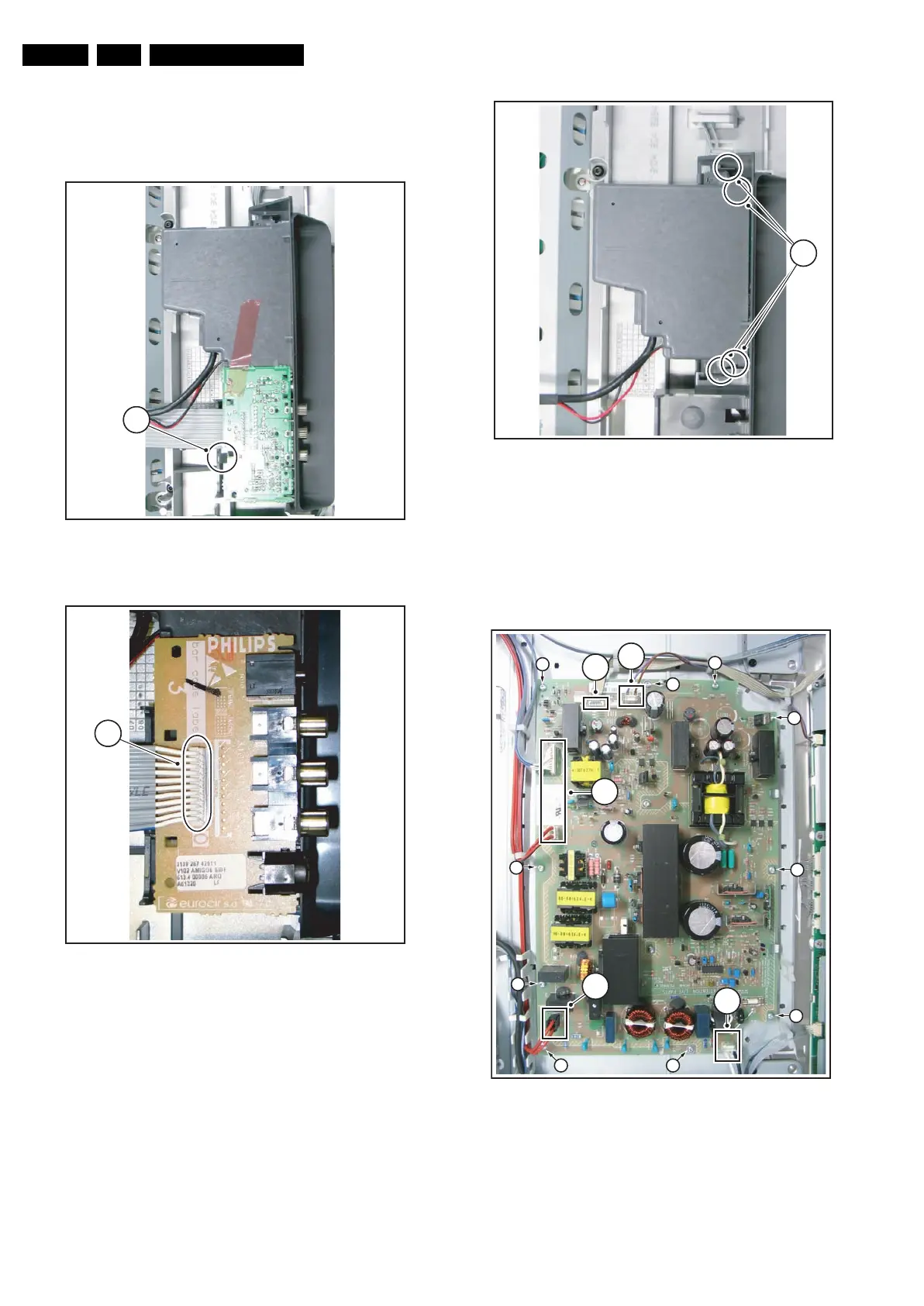
4.3.6 Sanken Display Supply Panel
1. Mark connector [1] to avoid erroneous re-assembly.
2. Unplug connectors [1][2] from the panel.
3. Remove screws [3].
4. Take the panel out (it hinges on the right side).
Figure 4-10 Sanken Display Supply Panel
The Sanken Display Supply Panel comes as a buy-in panel
and is a black-box for Service. When defective, replace the
whole panel.
G_15990_149.eps
120506
1
G_15990_150.eps
120506
2
G_15990_151.eps
120506
1
G_15910_016.eps
230606
3
3
3
3
3
33
3
3
3
1
2
2
2
2