Technical Specifications, Connections, and Chassis Overview
EN 3BJ2.4U/BJ2.5U LA 1.
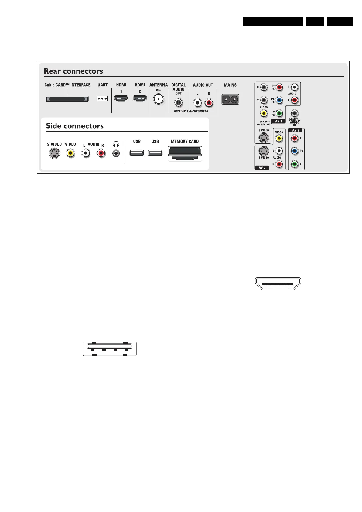
1.2 Connection Overview
Figure 1-1 Side and rear I/O connections 42” models
Note: The following connector color abbreviations are used
(acc. to DIN/IEC 757): Bk= Black, Bu= Blue, Gn= Green, Gy=
Grey, Rd= Red, Wh= White, and Ye= Yellow.
1.2.1 Side Connections
Headphone (Output)
Bk - Headphone 32 - 600 ohm / 10 mW ot
Cinch: Video CVBS - In, Audio - In
Rd - Audio R 0.5 V
RMS
/ 10 kohm jq
Wh - Audio L 0.5 V
RMS
/ 10 kohm jq
Ye - Video CVBS 1 V
PP
/ 75 ohm jq
SVHS (Hosiden): Video Y/C - In
1 - Ground Y Gnd H
2 - Ground C Gnd H
3 - Video Y 1 V
PP
/ 75 ohm j
4 - Video C 0.3 V
PP
P / 75 ohm j
USB2.0
Figure 1-2 USB (type A)
1-+5V k
2 - Data (-) jk
3 - Data (+) jk
4 - Ground Gnd H
1.2.2 Digital Media Reader with USB2.0 (for 42” sets)
In 42” sets, a 6-in-1 card reader unit is available, which is
connected via USB to the Small Signal Board (see also par.
“Technical Specifications” -> “Multimedia”).
This unit also contains two USB2.0 connectors.
1.2.3 Rear Connections
POD: CableCARD Interface
68p - See diagram B10A jk
Service Connector (UART)
1 - UART_TX Transmit k
2 - Ground Gnd H
3 - UART_RX Receive j
HDMI 1 & 2: Digital Video, Digital Audio - In
Figure 1-3 HDMI (type A) connector
1 - D2+ Data channel j
2 - Shield Gnd H
3 - D2- Data channel j
4 - D1+ Data channel j
5 - Shield Gnd H
6 - D1- Data channel j
7 - D0+ Data channel j
8 - Shield Gnd H
9 - D0- Data channel j
10 - CLK+ Data channel j
11 - Shield Gnd H
12 - CLK- Data channel j
13 - n.c.
14 - n.c.
15 - DDC_SCL DDC clock j
16 - DDC_SDA DDC data jk
17 - Ground Gnd H
18 - +5V j
19 - HPD Hot Plug Detect j
20 - Ground Gnd H
Aerial - In
- - F-type (US) Coax, 75 ohm D
G_15910_027.eps
230606
1234
E_06532_022.eps
300904
19
1
18 2
E_06532_017.eps
250505