Mechanical Instructions
EN 11BJ2.4U/BJ2.5U LA 4.
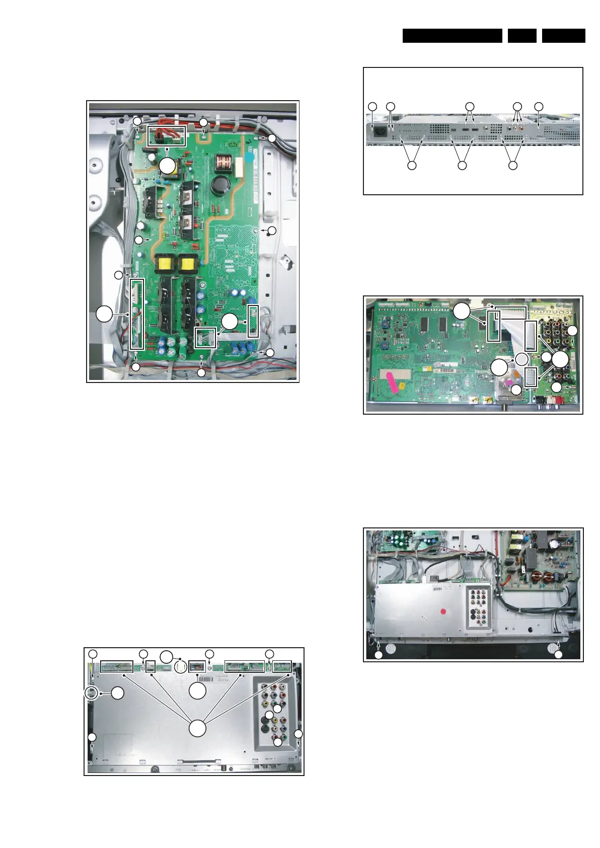
4.3.7 Platform Supply Panel
See figure “Supply Panel” for details.
Figure 4-11 Supply Panel
1. Unplug connectors [1].
2. Remove screws [2].
3. Take the panel out (it hinges at the left side).
4.3.8 Small Signal Board (SSB) and Main I/O Panel
Caution: it is absolutely mandatory to remount all different
screws at their original position during re-assembly. Failure to
do so may result in damaging the SSB.
1. Unplug connector [1]. See figure “Rear SSB shield”.
2. Unplug USB connector [2].
3. Remove black clip from LVDS connector.
4. Carefully unplug the fragile LVDS connector.
5. Remove screws [5] and [6]. See figure “Bottom SSB
shield”.
6. Remove rear and bottom shield.
7. Unplug connectors [7].
8. Remove screws [8].
9. Remove SSB from the set.
Figure 4-12 Rear SSB shield
Figure 4-13 Bottom SSB shield
For removing Rear I/O Panel (see figure “Rear I/O”):
1. Unplug connector [9].
2. Remove screws [10].
3. Remove the panel from the set.
Figure 4-14 Rear I/O panel
4.3.9 Subframe Lift
Before the LCD Display Panel, the AmbiLight Diffusor Frame
and/or the LED Panel can be taken out, the Subframe must be
lifted.
Figure 4-15 SSB lift -1-
1. Remove screws [1].
2. Lift the SSB without unplugging the connectors; put the
SSB upwards-down.
G_15910_017.eps
230606
1
1
1
2
2
2
2
2
2
2
3
2
G_15930_078.eps
190606
4
2
1
5
5
5
5
555
5
5
3
G_15930_079.eps
190606
6 6
6 6 6
6 6 6
G_15930_080.eps
190606
10
10
10
10
9
7
8
G_15910_018.eps
230606
1
1