Service Modes, Error Codes, and Fault Finding
EN 21BJ2.4U/BJ2.5U LA 5.
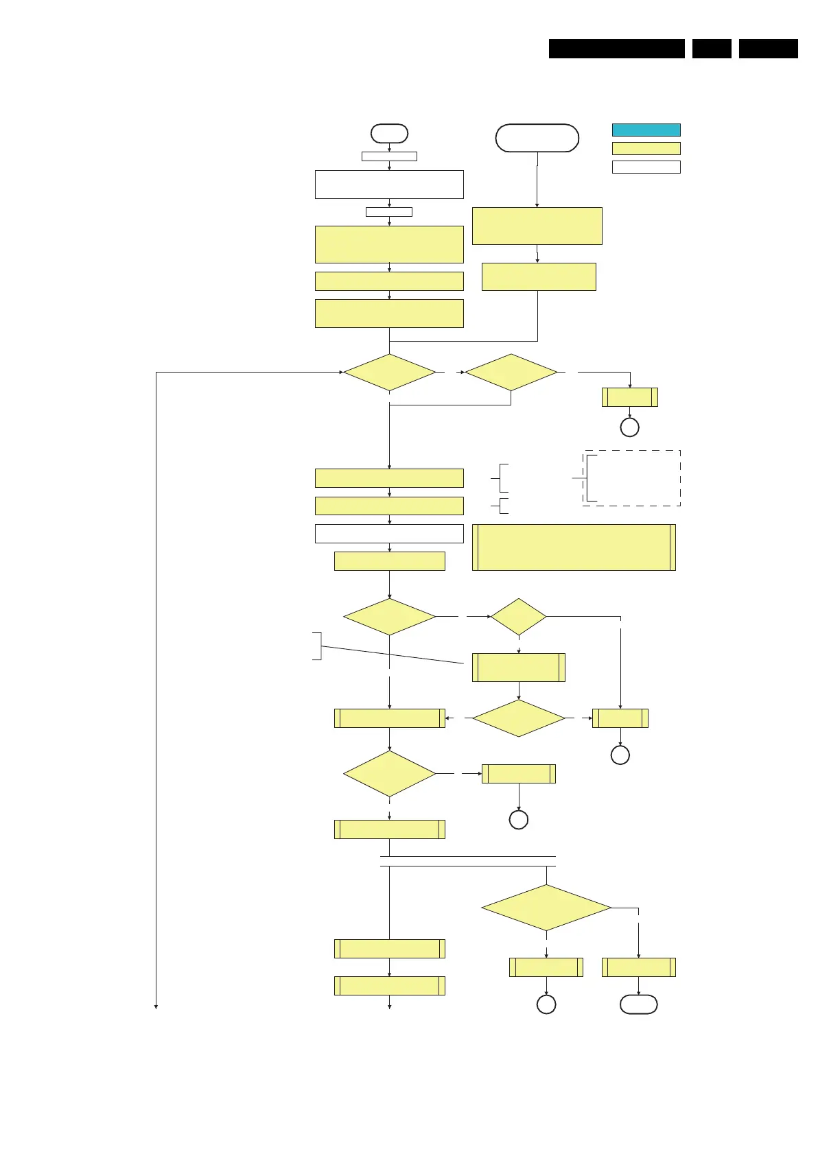
Figure 5-6 “Off” to “Semi Stand-by” flowchart (part 1)
All I/O lines have a “high” default state:
- Assert the Viper reset.
- Sound-Enable and Reset-Audio should remain “high”.
- NVM power line is “high”, no NVM communication possible.
Off
Standby Supply starts running.
+5V2, 1V2Stb, 3V3Stb and +2V5D become present.
In case of PDP 3V3 Vpr to CPU PDP becomes present.
st-by µP resets
Stand-by or
Protection
Mains is applied
- Switch Sound-Enable and Reset-Audio “high”.
They are “low” in the standby mode if the
standby mode lasted longer than 2s.
Enable the +1V2 supply (ENABLE-1V2)
detect-5V
received within
2900 ms after POD-MODE
toggle?
No
Yes
activate +5V supply detection algorithm
+12V error
detect-12VSW received within
2900 ms after POD-mode
toggle?
No
SP
activate +12VSW supply
detection algorithm
Yes
+5V, +8V6, +12VS, +12VSW and Vsound are switched on
Switch “on” all supplies by switching LOW the POD-MODE
and the ON-MODE I/O lines.
Initialise I/O pins of the st-by µP, start keyboard scanning, RC
detection, P50 decoding. Wake up reasons are “off”.
If the protection state was left by short circuiting the
SDM pins, detection of a protection condition during
startup will stall the startup. Protection conditions in a
playing set will be ignored. The protection mode will
not be entered.
In case of FHP PDP: Switch PDPGO “low”
CPUGO (inverse of the stby I/O line POD-MODE) and PDPGO
are then both “low” and the PDP is in the “low power” mode.
Switching the POD-MODE
low in an FHP PDP set
makes the CPUGO go “high”
and starts the PDP CPU.
except in an FHP PDP Cold
Boot
FHP PDP Set?
Switch PDPGO high:
PDP should start: 5V, 8V6 and
12V are activated
Yes
No
+5V error
detect-5V
received within
2900 ms after PDPGO
toggle?
No
SP
SP
Yes
Switching the PDPGO “high”
will give a visual artefact and
should only be done if really
necessary.
Switching the POD-MODE and the
“on” mode “low” in an SDI PDP set
makes the PDP supplies go to the
“on” mode. Within 4 seconds, a
valid LVDS must be sent to the
display to prevent protection.
(valid for V3 version)
Wait 50ms and then start polling the detect-
5V, detect-8V6 and detect-12V every 40ms.
The availability of the supplies is checked through detect signals (delivered by
dedicated detect-IC's) going to the st-by µP. These signals are available for
+12V, +8V6, +5V, +1V2 and +2V5. A low to high transition of the signals should
occur within a certain time after toggling the standby line. If an observers is
detected before the time-out elapses, of course, the process should continue in
order to minimize start up time.
Start polling the detect-1V2 every 40ms
Switch “low” the NVM power reset line. Add a 2ms delay
before trying to address the NVM to allow correct NVM
initialization.
+8V6 error
detect-8V6 received
within 6300 ms after POD-mode toggle?
Startup shall not wait for this detection
and continue startup.
No
SP
No need to wait for the 8V6 detection at this point.
activate +8V6 supply
detection algorithm
Yes
return
ECO Baby Jaguar??
Auto Protection
Line High??
Audio Error
Yes Yes
No
F_15400_096a.eps
230606
To part B To part B
autonomous action
action holder: St-by
action holder: MIPS
Only applicable for sets with CableCARD
TM
slot (POD)
*
*
*
*
*
*
*