Service Modes, Error Codes, and Fault Finding
EN 21JL2.1E AA 5.
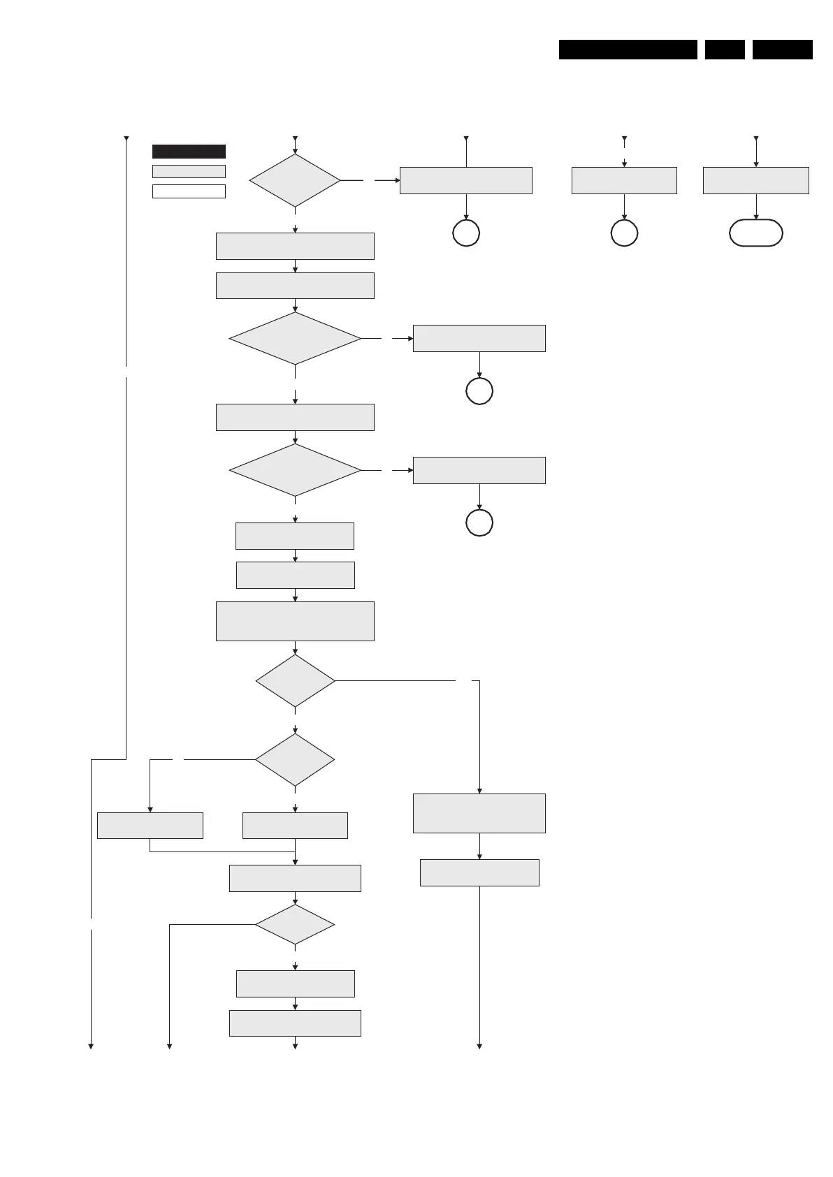
Figure 5-4 “Off” to “Semi Stand-by” flowchart (part 2)
F_15710_152b.eps
200905
No
Release Viper reset
Feed cold boot script (1)
Release Viper reset
Feed initializing boot script (3)
disable alive mechanism
Detect EJTAG debug probe
(pulling pin of the probe interface to
ground by inserting EJTAG probe)
EJTAG probe
connected ?
No
Yes
Bootscript ready
in 1250 ms?
Yes
No
Release Viper reset
Feed warm boot script (2)
Cold boot?
Yes
No
RPC start (comm. protocol)
Set I²C slave address
of Standby µP to (A0h)
Set I²C slave address
of Standby µP to (64h)
Release PNX2015 reset 100ms after
Viper reset is released
Release PNX2015 reset 100ms
after Viper reset is released
+2.5V or +3.3V errorNo
Yes
Activate supply detection algorithms for
+1.2V, +2.5V and +3.3V
Enable the DC/DC converters for
+2.5V and +3.3V.
+1.2V error
Detect-1V2
received within
250ms?
No
Yes
SP
SP
Start polling the detect-2V5
and detect-3V3 every 40ms.
Detect-2V5 and
detect-3V3 received within
250 ms?
Enable the supply fault detection
interrupt
Supply fault errorNo
Yes
SP
SUPPLY-FAULT I/O line
is “high”?
+8V6 error
No
SP
activate +8V6 supply
detection algorithm
return
action holder: MIPS
autonomous action
action holder: St-by
From part AFrom part A From part A From part A From part A
To part CTo part C To part C To part C