Service Modes, Error Codes, and Fault Finding
EN 22 JL2.1E AA5.
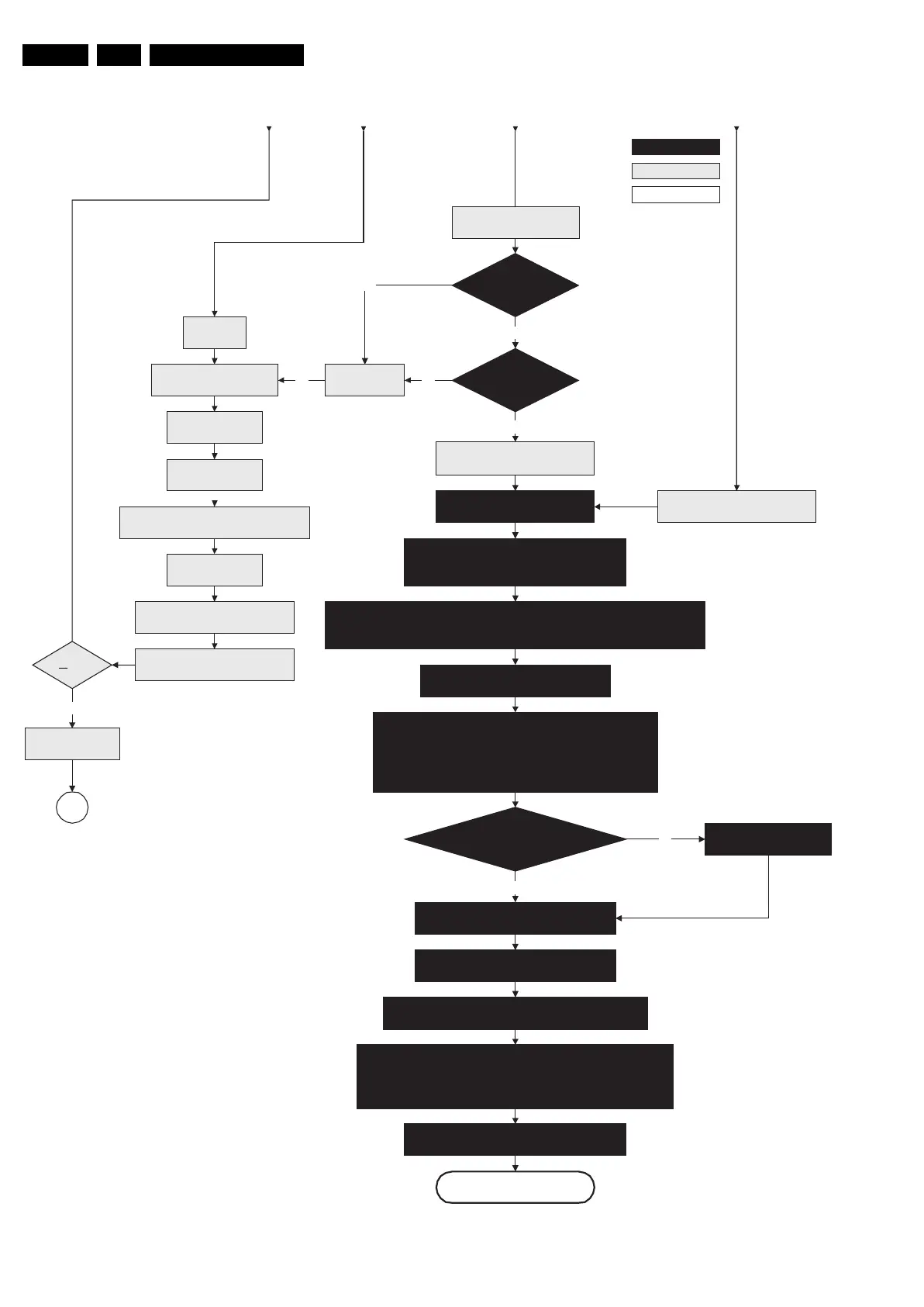
Figure 5-5 “Off” to “Semi Stand-by” flowchart (part 3)
F_15710_152c.eps
200905
Yes
MIPS reads the wake up reason
from standby µP.
Semi-Standby
Initialize MPIF's .
MPIF should deliver 4 observers:
POR= 0; normal operation
MSUP= 1: Main supply is present
ASUP= 1; audio supply is present
ROK= 1; reference frequency is present (coming from AVIP)
(AVIPs need to be started before the MPIF's in order to have a good clock distribution).
AVIP default power-up mode is Standby. The Viper instructs AVIP via I²C to enable all the
PLLs and clocks and hence enter to Full Power mode.
Initialize tuners and Hirate
All observers present with correct state?
Log appropriate
Observer error
No
Yes
Initialize video processing ICs:
- Spider
Initialize source selection
Initialize Columbus
Initialize 3D Combfilter
Initialize AutoTV
3-th retry?
Log Code as
error code
SP
Enable Alive check mechanism
Wait until Viper starts to
communicate
No
Yes
Initialize PNX2015 HD subsystem
Switch POD-MODE and ON-MODE
I/O line “high”.
Disable all supply related protections and
switch “off” the +2V5, +3V3 DC/DC converter.
Switch “off” the remaining DC/DC
converters
Wait 5ms
Switch Viper in reset
Wait 10ms
Switch the NVM reset
line “high”.
Viper SW initialization
succeeded
within 20s?
No
Flash to RAM image
transfer succeeded
within 30s?
No
Yes
Code = 53
Code = 5
Wait for the +8V6 to be detected if not yet present.
(if it does not come, the standby µP will enter a
protection mode)
Initialize Ambilight with Lights “off”.
From part B From part B From part BFrom part B
action holder: MIPS
autonomous action
action holder: St-by
RPC start (comm. protocol)