Service Modes, Error Codes, and Fault Finding
EN 26 JL2.1E AA5.
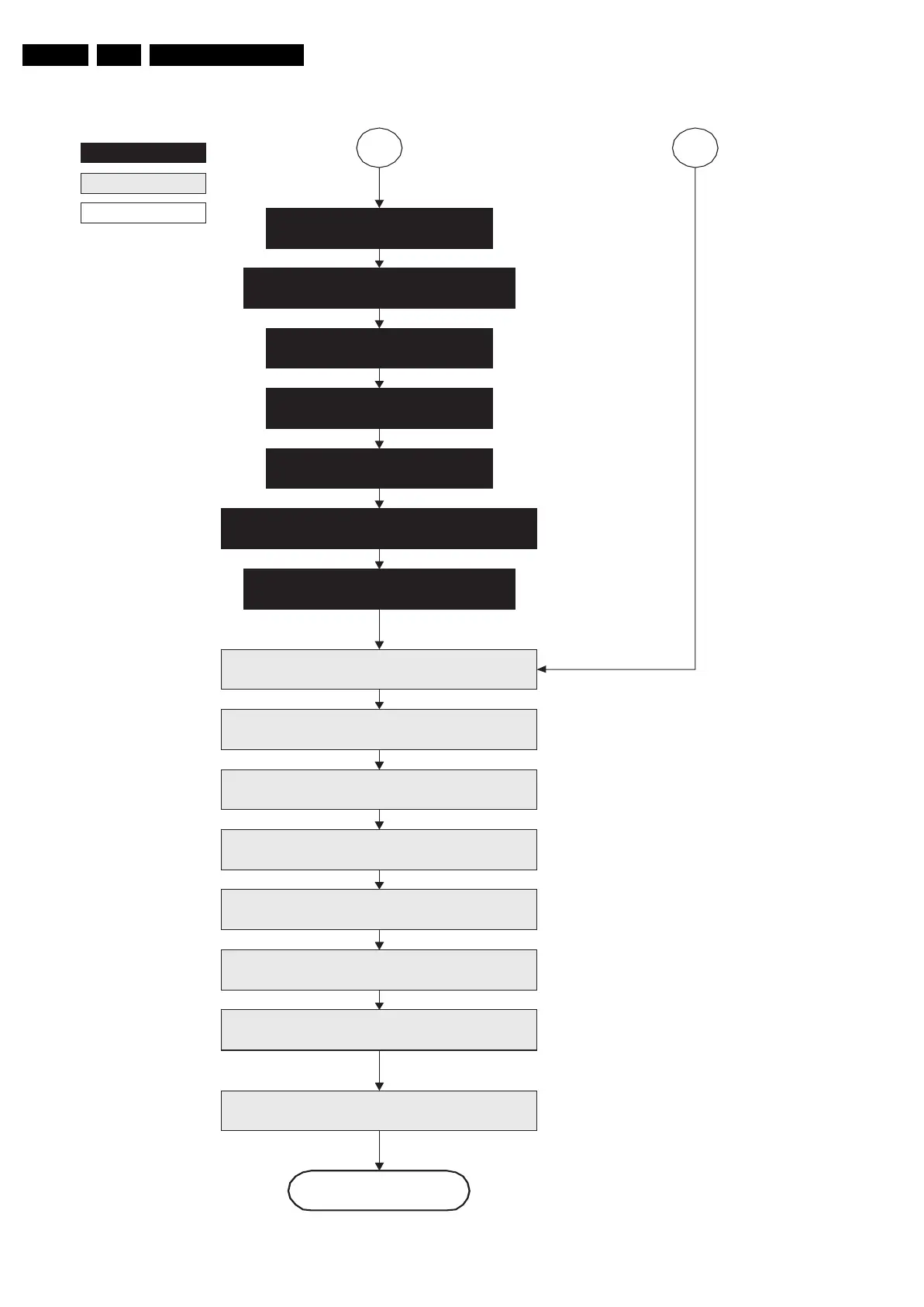
Figure 5-9 “Protection” flowchart
autonomous action
action holder: St-by
action holder: MIPS
F_15710_156.eps
200905
Switch “off” remaining DC/DC converters
Switch “off” all supplies by switching “high”
the ON-MODE I/O lines
Protection
MP
Flash LED in order to indicate protection state *
(*): This can be the standby LED or the ON LED
depending on the availability in the set under
discussion.
SP
off.
Disable all supply related protections and switch
“off” the +2V5, +3V3 DC/DC converter
Switch Viper in reset state
Wait 5ms
Wait 10ms
Switch the NVM reset line “high”
Redefine wake up reasons for protection
state and transfer to stand-by µP
Log the appropriate error and
set stand-by flag in NVM
Ask stand-by µP to enter protection state
Switch “off” LCD lamp supply
Wait 250ms (min. = 200ms)
Switch “off” LVDS signal
Switch “off” 12V LCD supply within a time frame
of min. 0.5ms to max. 50ms after LVDS switch