Service Modes, Error Codes, and Fault Finding
EN 25JL2.1E AA 5.
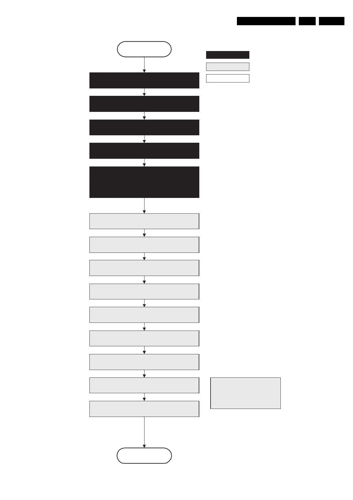
Figure 5-8 “Semi Stand-by” to “Stand-by” flowchart
autonomous action
action holder: St-by
action holder: MIPS
F_15710_155.eps
200905
Stand by
Semi Stand by
DDR-RAM is put in self refresh mode and the images
are kept in the hibernating DDR-RAM.
Important remark:
release reset audio and sound-
enable 2 sec after entering
standby to save power
Disable all supply related protections and switch
“off” the +2V5, +3V3 DC/DC converter.
Switch Viper in reset state
Switch “off” the remaining DC/DC converters
Wait 5ms
Wait 5ms
Wait 10ms
Switch the NVM reset line “high”
Switch “off” all supplies by switching “high”
the ON-MODE I/O lines.
*) If this is not performed and the set is
switched to standby when the ramping of
the EPLD is still ongoing, the lights will
remain lit in standby.
Transfer Wake up reasons to the Standby µP.
Images are re-transferred to DDR-RAM from
Flash RAM (verification through checksum)
MIPS image completes the application reload,
stops DDR-RAM access, puts itself in a
sleepmode and signals the standby µP when the
standby mode can be entered.
Delay transition until ramping down of ambient light is
finished. *)
Switch ambient light to passive mode with RGB
values on zero. *)