3-2
3-2
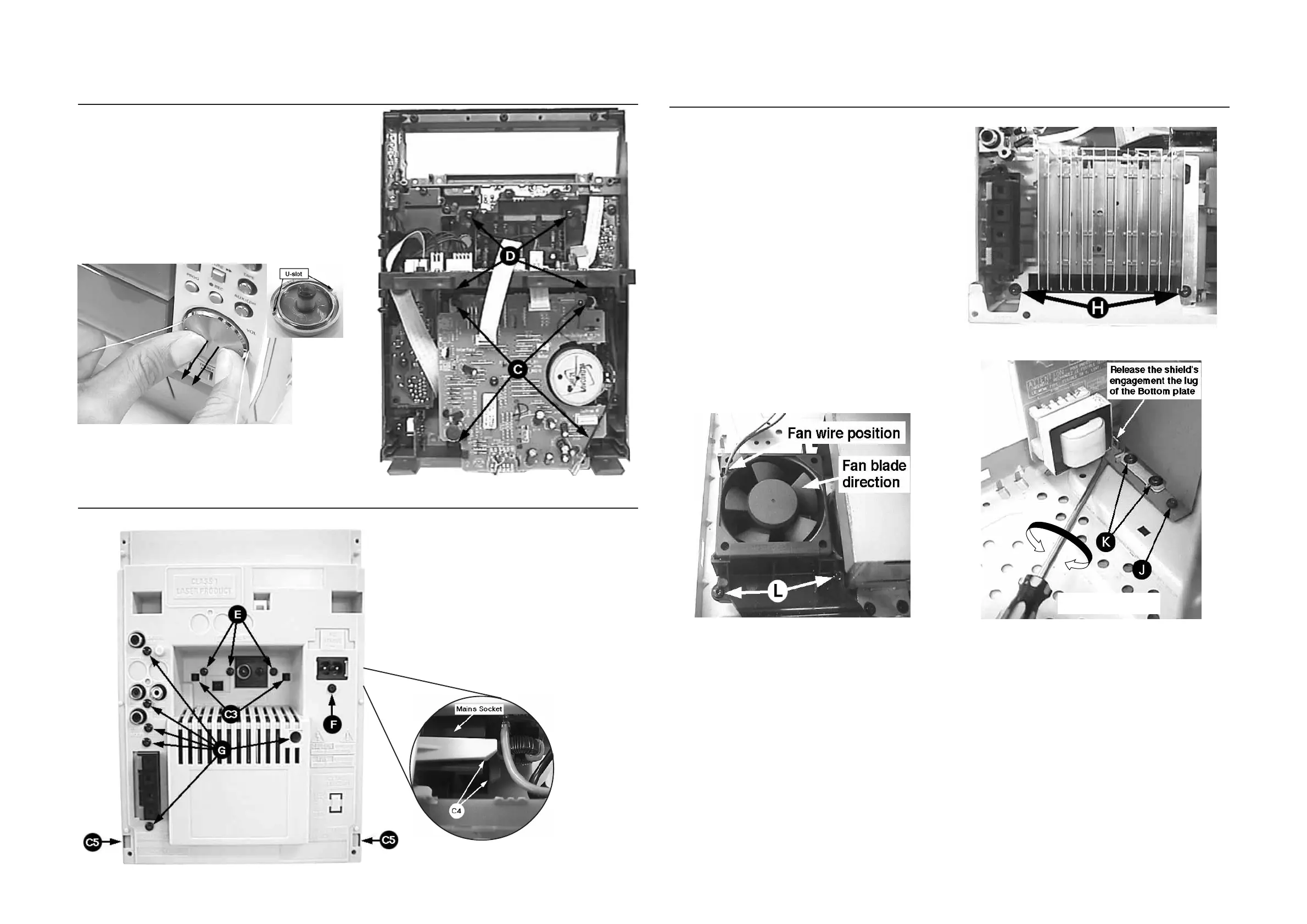
Dismantling of the Front Panel assembly
1) Loosen 4 screws C in figure 7 to remove the ETF6-LE
Module.
2) Insert a strong string into the slot between the Jog knob
(pos 136) and Cover control (pos 137), looped it until it
engage into both the U-slot of the Jog knob and pulled it out
as shown in figure 6.
3) Loosen 4 screws D to remove the Display Board assembly.
Figure 7
Figure 6
Jog knob
Dismantling of the Bottom assembly
1) Loosen 2 screws H as shown in figure 9 to remove the
Combi / Regulator boards assembly.
2) Loosen1 screws J and uncatch Shield Transformer from
the Bottom plate (pos 265) as shown in figure 11 to
remove it.
3) Loosen 4 screws K mounting the Mains Transformer to
remove the Mains Board & Transformer assembly.
4) Loosen 2 screws L to remove the Housing Fan top (pos
267).
Note: During Fan replacement care should be taken to
ensure that the following are correct:
- fan blades direction
- fan wire position
- fan is properly supported by the rubber damper
Figure 9
Figure 10
Twist screw driver
Figure 11
Dismantling of Rear Panel
Figure 8
1) Loosen 3 screws E and 2 catches C3 to remove the Tuner
Board assembly.
Note: Tuner Board assembly can also be remove to-
gether with the Panel Rear.
2) Loosen 1 screw F and the 2 catches C4 to free the Mains
socket board from the Panel Rear (pos 256).
3) Loosen 6 screws G and 2 catches C5 to remove the
Panel Rear (pos 256) by sliding it out towards the rear.
www.freeservicemanuals.info