11-1
11-1
MAINS BOARD
TABLE OF CONTENTS
Brief introduction on Mains Board ................................. 11-1
Socket part..................................................................... 11-1
Mains part - Circuit diagram .......................................... 11-2
Mains part - Copper side view ....................................... 11-3
Mains part - Component side view ................................ 11-4
Electrical parts list.......................................................... 11-5
1100
1
2
T341 A1
T342 A1
12
12
AA
1100 A1
1120 A2
1121 A2
5107 A1
9102 A1
9104 A1
1121
1
5107 *
9102 *
9104 *
1120
1
8239_210_88360 ... 3438 pt 1 dd wk103
/37
-
x
x
/22
x
-
-
Item *
5107
9102
9104
This assembly drawing shows all possible versions.
For components used in a spsecific version see
schematic diagram and respective parts lists.
3139 113 3438 pt 1 dd wk 103
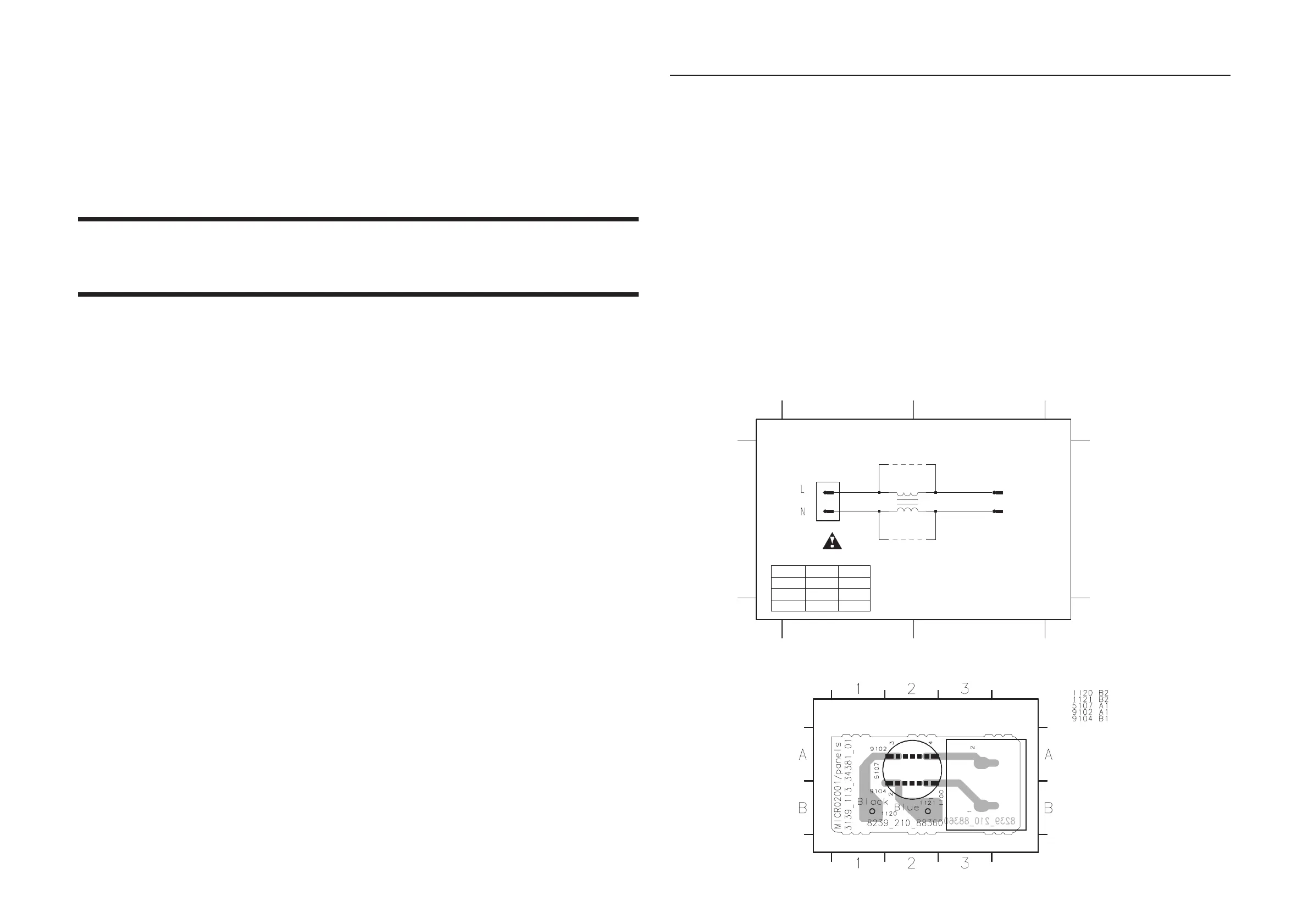
SOCKET PART - CIRCUIT DIAGRAM & COMPONENT LAYOUT
Brief introduction of the Mains Board
ECO Power
Standby Transformer 5100 provides the LPS supply to control the relay 1102, cutting of the Mains supply to the Mains transformer
during the ECO Power (standby) mode.
The Mains transformer provides the following:
- AC supply (across F1 & F2) and -Vkk supply for the FTD display
- +A and +A/2 to the Main amplifier area and Regulator board
www.freeservicemanuals.info