Alignments
EN 48 Q552.2E LA6.
2011-Jun-01
back to
div. table
Note
1). Example
6.5 Reset of Repaired SSB
A very important issue towards a repaired SSB from a Service
repair shop (SSB repair on component level) implies the reset
of the NVM on the SSB.
A repaired SSB in Service should get the service Set type
“00PF0000000000” and Production code “00000000000000”.
Also the virgin bit is to be set. To set all this, you can use the
ComPair tool or use the “NVM editor” and “Dealer options”
items in SAM (do not forget to “store”).
After a repaired SSB has been mounted in the set (set repair
on board level), the type number (CTN) and production code of
the TV has to be set according to the type plate of the set. For
this, you can use the NVM editor in SAM. This action also
ensures the correct functioning of the “Net TV” feature and
access to the Net TV portals. The loading of the CTN and
production code can also be done via ComPair (Model number
programming).
After a SSB repair, the original channel map can be restored,
provided that the original channel map was stored on a USB
stick before repair was commenced and that basic functionality
of the TV, needed for this procedure, was not hampered as a
result of the defect. The procedure of “channel map cloning” is
clearly described in the (electronic) user manual.
In case of a display replacement, reset the “Operation hours
display” to “0”, or to the operation hours of the replacement
display.
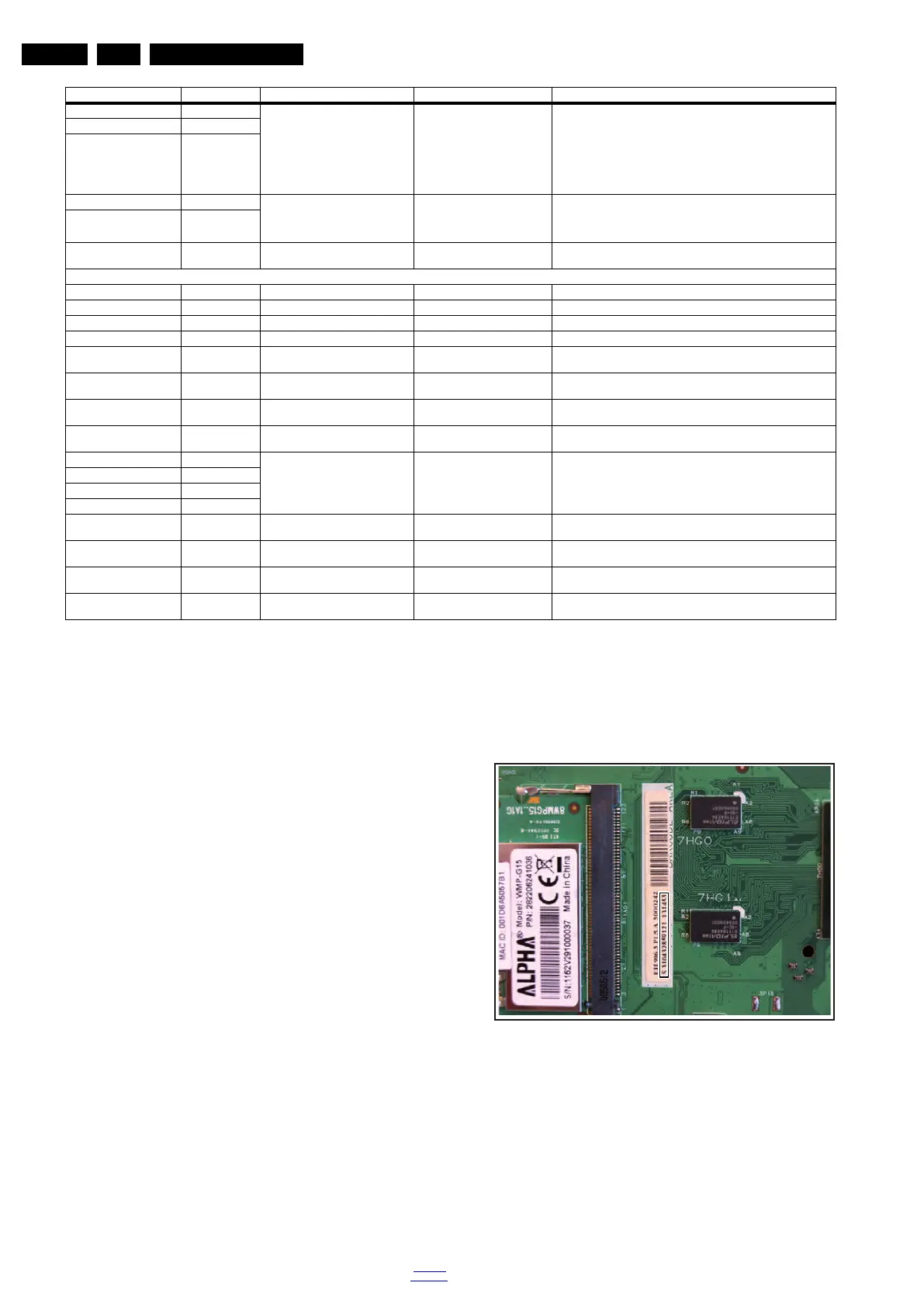
6.5.1 SSB identification
Whenever ordering a new SSB, it should be noted that the
correct ordering number (12nc) of a SSB is located on a sticker
on the SSB. The format is <12nc SSB><serial number>. The
ordering number of a “Service” SSB is the same as the ordering
number of an initial “factory” SSB.
Figure 6-1 SSB identification
Bit 5 32 Temp LUT 000
1)
000 = temp lut 0
001 = temp lut 1
010 = temp lut 2
011 = temp lut 3
100 = future use
101 = future use
110 = future use
111 = future use
Bit 4 16
Bit 3 8
Bit 2 4 Temp Sensor 00
1)
00 = no temp sensor
01 = temp sensor in display
10 = temp sensor on additional board
11 = temp sensor in AL module
Bit 1 2
Bit 0 (LSB) 1 FAN 0
1)
0 = no fan
1 = fan(s) present)
Option 8 (prescribed value 00012
1)
)
Bit 15 (MSB) 32768 Test 8 0
1)
-
Bit 14 16384 Test 7 0
1)
-
Bit 13 8192 Test 6 0
1)
-
Bit 12 4096 Test 5 0
1)
-
Bit 11 2048 Test 4 (Trick Mode) 0
1)
0 = OFF
1 = ON
Bit 10 1024 Test 3 (XRay) 0
1)
0 = OFF
1 = ON
Bit 9 512 Test 2 (DBV-T light) 0
1)
0 = OFF
1 = ON
Bit 8 256 Test 1 (Monitor out) 0
1)
0 = OFF
1 = ON
Bit 7 128 not used 0000
1)
-
Bit 6 64
Bit 5 32
Bit 4 16
Bit 3 8 WM DRM10 1
1)
0 = OFF
1 = ON
Bit 2 4 HBBTV 1
1)
0 = OFF
1 = ON
Bit 1 2 DVB-T2 Installation 0
1)
0 = OFF
1 = ON
Bit 0 (LSB) 1 DVB-T2 0
1)
0 = OFF
1 = ON
Option & Bit Dec. Value Option Name Prescribed Value
1)
Description
18310_221_090318.eps
090319