Circuit Descriptions
EN 55Q552.2E LA 7.
2011-Jun-01
back to
div. table
• the output signal on the +V-LNB line goes to the LNBH23Q
(item no. 7T50)
• the LNBH23Q (item no. 7T50) sends a feedback signal via
the V0-CNTRL line
• the switching frequency of the +5V-DVBS to +1-DVBS
switched mode converter is 900 kHz (item no. 7T00)
• a delay line for the +2V5-DVBS and +1V-DVBS lines is
created with item no. 3T03 (R=10k) and 2T06 (C=100n)
• a 3.3V to 2.5V linear stabiliser is built around item no. 7T01
• a 5V to 3.3V linear stabiliser is built around item no. 7T02.
Diagram B08B contains the DVB-S2 LNB supply:
• the +V-LNB signal comes from item no. 7T03
• the V0-CTRL signal goes to item no. 7T03
• the LNB-RF1 goes to the LNB.
Figures gives a graphical representation of the DC/DC
converters with its current consumptions:
Figure 7-6 DC/DC converters
7.4 Front-End Analogue and DVB-T, DVB-C;
ISDB-T reception
7.4.1 European/China region
The Front-End for the European/China region consist of the
following key components:
• Hybrid Tuner
• Switchable SAW filter 7/8 MHz (Eur.), or single SAW filter
(8 MHz) (China)
• Bandpass filter
• Amplifier
• PNX855xx SoC TV processor with integrated DVB-T and
DVB-C channel decoder and analogue demodulator.
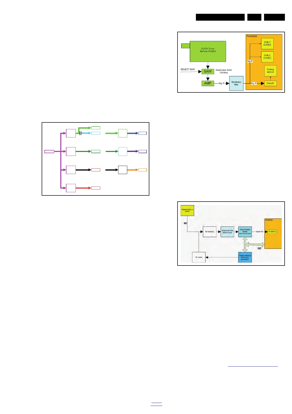
Below find a block diagram of the front-end application for this
region.
Figure 7-7 Front-End block diagram European/China region
7.5 Front-End DVB-S(2) reception
The Front-End for the DVB-S(2) application consist of the
following key components:
• Satellite Tuner; I
2
C address 0xC6 (bridged via channel
decoder)
• Channel decoder; I
2
C address 0xD0
• LNB switching regulator; I
2
C address 0x14
•Amplifier
• PNX855xx SoC TV processor with integrated DVB-T and
DVB-C channel decoder and analogue demodulator.
Below find a block diagram of the front-end application for
DVB-S(2) reception.
Figure 7-8 Front-End block diagram DVB-S(2) reception
This application supports the following protocols:
• Polarization selection via supply voltage (18V = horizontal,
13V = vertical)
• Band selection via “toneburst” (22 kHz): tone “on” = “high”
band, tone “off” = “low” band
• Satellite (LNB) selection via DiSEqC 1.0 protocol
• Reception of DVB-S (supporting QPSK encoded signals)
and DVB-S2 (supporting QPSK, 8PSK, 16APSK and
32APSK encoded signals), introducing LDPC low-density
parity check techniques.
7.6 HDMI
In this platform, the Silicon Image Sil9x87 HDMI multiplexer is
implemented. Refer to figure 7-9 HDMI input configuration
for
the application.
18770_226_100127.eps
100426
+5V5-TUN
196 mA
+5V
+5V5-TUN +5V-TUN
2179 mA 196 mA
+12V +3V 3
+3V 3 +2V5
2919 mA 2371 mA 450 mA
+1V8
+1V8 +1V2
2450 mA 550 mA
+1V1
5100 mA
+1V1
dc-dc
18770_235_100127.eps
100219
18770_237_100127.eps
100219