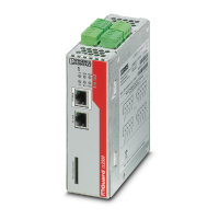
FL MGUARD RS2000 TX/TX-B
105656_en_05 PHOENIX CONTACT 105
The switching inputs and switching outputs can be connected with signals from external de-
vices, e.g., with signals from PLCs. In this case, ensure the same potential as well as voltage
and current specifications are defined.
Depending on the firmware version used, the service contacts can be used for various
switching or signaling tasks.
Service contacts as of firmware version 8.1
Input/CMD I1, CMD I2 Via the web interface under “Management, Service I/O”, you can set whether a push button
or an on/off switch has been connected to the inputs. One or more freely selectable VPN
connections or firewall rule records can be switched via the corresponding switch. A mixture
of VPN connections and firewall rule records is also possible. The web interface displays
which VPN connections and which firewall rule records are connected to this input.
The push button or on/off switch is used to establish and release predefined VPN connec-
tions or the defined firewall rule records.
Operating a connected
push button
• To switch on the selected VPN connections or firewall rule records, press and hold the
push button for a few seconds and then release the push button.
• To switch off the selected VPN connections or firewall rule records, press and hold the
push button for a few seconds and then release the push button.
Operating a connected
on/off switch
• To switch on the selected VPN connections or firewall rule records, set the switch to
ON.
• To switch off the selected VPN connections or firewall rule records, set the switch to
OFF.
Signal contact (signal out-
put) O1, O2 resp. ACK
Via the web interface under “Management, Service I/O” you can set whether certain VPN
connections or firewall rule records are monitored and displayed via the LED Info 1 (out-
put/O1 resp. ACK) or LED Info 2 (output/O2 resp. ACK).
If VPN connections are being monitored, an illuminated Info LED indicates that VPN con-
nections are established.
Alarm output O4 resp.
FAULT
The O4 alarm output monitors the function of the device and therefore enables remote di-
agnostics.
The Fault LED lights up red if the signal output changes to the low level due to an error (in-
verted control logic).
The O4 alarm output reports the following when “Management, Service I/O, Alarm output”
has been activated.
– Monitoring of the link status of the Ethernet connections
– Monitoring of the temperature condition
– Monitoring of the connection state of the internal modem
 Loading...