TC MGUARD RS4000/RS2000 3G
105656_en_05 PHOENIX CONTACT 59
3.3 Installation of TC MGUARD RS4000/RS2000 3G
3.3.1 Mounting/removal
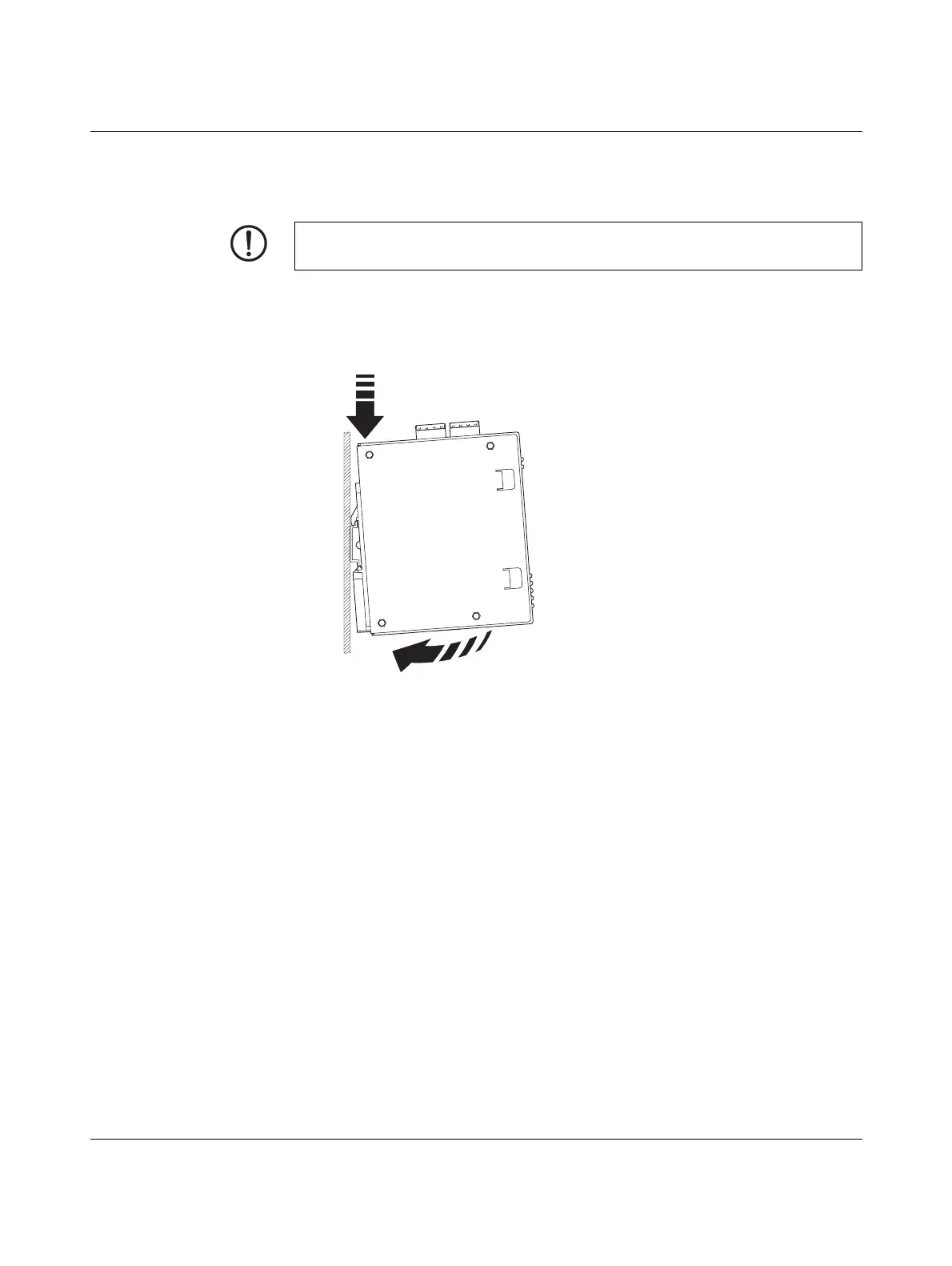
Mounting The device is ready to operate when it is supplied. The recommended sequence for mount-
ing and connection is as follows:
• Mount the TC MGUARD RS4000/RS2000 3G on a grounded 35 mm DIN rail according
to DIN EN 60715.
Figure 3-3 Mounting the TC MGUARD RS4000/RS2000 3G on a DIN rail
• Attach the top snap-on foot of the TC MGUARD RS4000/RS2000 3G to the DIN rail
and then press the TC MGUARD RS4000/RS2000 3G down towards the DIN rail until
it engages with a click.
Removal • Remove or disconnect the connections.
• To remove the TC MGUARD RS4000/RS2000 3G from the DIN rail, insert a screw-
driver horizontally in the locking slide under the housing, pull it down – without tilting the
screwdriver – and then pull up the TC MGUARD RS4000/RS2000 3G.
NOTE: Device damage
Only mount and remove devices when the power supply is disconnected.
 Loading...