© PSI (Photon Systems Instruments), spol. s r. o.
29
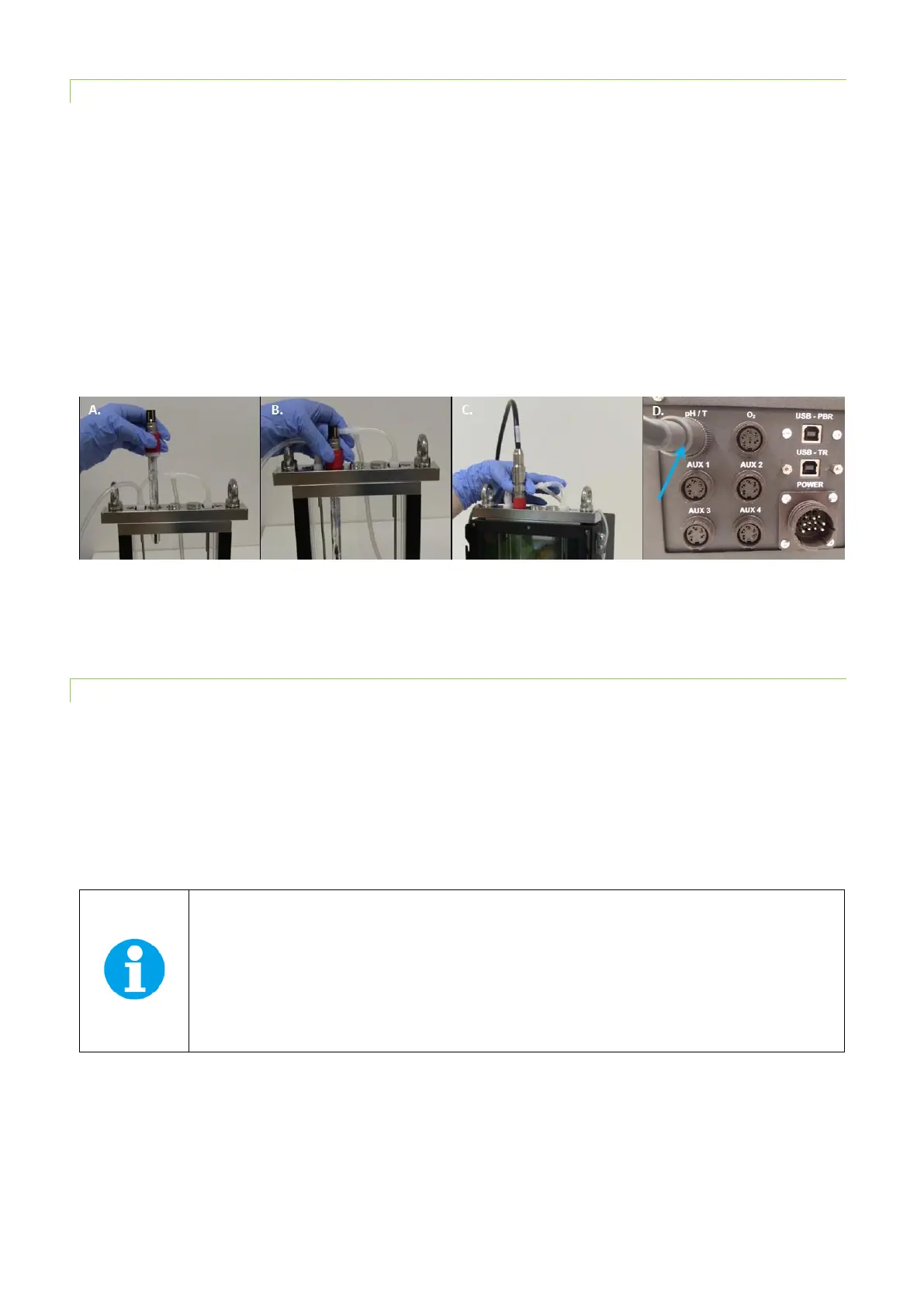
4.3.1 INSTALLATION
• Open one of the large ports in the lid by unscrewing one of the steel screws in the lid.
• Insert the pH electrode into the open port and secure it tightly with a plastic ring around the probe (Fig. 16A,B).
Note: Any position in the lid can be selected for the pH/Temperature sensor. However, we recommend placing
the O
2
sensor in the far right connector of the vessel, where magnetic stirrer provides most homogeneous mixing
of the media.
• Attach the cable labeled “pH” to the pH/Temperature electrode (Fig. 16C).
• Connect the connector cable with the PBR FMT150 (Fig. 16D).
• When connected to the PBR FMT150 control unit, sensor unit is automatically recognized. The function of the
pH/temperature sensor can be controlled manually by the front panel of the control unit and remotely via PBR
software. For manual control please refer to control menu tree on page 62 for more detail explanation.
Fig. 16 Installation of the pH/temperature sensor. A) Positioning the probe. B) Securing the probe. C) Attaching the cable to the
positioned probe. D) Attaching the cable to the rear side of the PBR.
4.3.2 PH CALIBRATION
Prior to initiation of each experiment it is recommended to perform the pH sensor calibration. The calibration can be done
either in PBR software (for more details see PBR Software manual) or using the FMT150 control unit front panel as
described below.
Follow these instructions during calibration:
• Go to operation menu using the front panel of the PBR control unit. In the operation menu go to
Setting > Calibration > Calibration pH.
If you have older versions of the electrodes InPro3253/120/PT1000 you need to connect the device
to earth during the process of calibration. For the new version of the electrode:
InPro3253SG/120/PT1000 calibration can be done without grounding. See Fig. 17C and D for
description of the grounding (For InPro3253/120/PT1000 version of the electrode, place one end of a
copper wire in the calibration solution and the other end fix under the metal clip on the PBR main
body as shown in Fig. 17C,D. Proceed with the calibration).