© PSI (Photon Systems Instruments), spol. s r. o.
37
Fig. 25 Assembly of the CO
2
electrode.
• Insert the CO
2
electrode into the appropriate vessel connector and secure it tightly (Fig. 26A).
Note: The position of the sensor in the lid is optional. In case other sensors are used, we recommend
to place the O
2
sensor to the right side of the vessel, where magnetic stirrer assures more
homogeneous mixing of the media this will leave the central position available for the CO
2
probe.
• Attach the cable of the dissolved CO
2
module to the CO
2
electrode (Fig. 26B).
• Connect the PBR FMT150 and the dissolved CO
2
module using a provided communication cable.
• Plug the communication cable into the “AUX IN” connector of the electronic box of the dissolved CO
2
module (Fig.
26C).
• Plug the other end of the communication cable into the “AUX1” connector at the rear of the Photobioreactor (Fig.
26D) or the AUX out of the additional components such as peristaltic pump as indicated in Fig. 10 on page 22 if
other optional components are included.
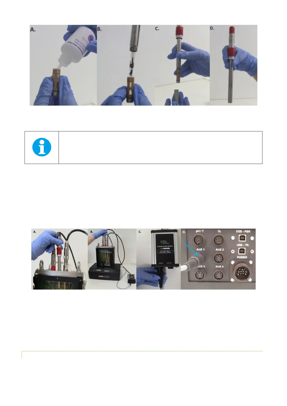
Fig. 26 Installation of the CO
2
sensor. A) Positioning the electrode. B) Attaching of the electronic module to the electrode. C) Attaching
of the communication cable to the “AUX IN” connector of electronic module. D) Attaching of the communication cable to the “AUX 1”
connector at the rear side of the PBR.
• The function of the CO
2
sensor can be controlled manually by the front panel of the control unit or by PBR
software. For manual control please refer to chapter 7.1 on page 62 for more detailed explanation.
5.5.2 CALIBRATION
To display CO
2
values as CO
2
concentration it is important to perform the calibration prior to the use of the electrode at
the temperature of the cultivation conditions.