C-863.12 Mercury Controller MS249E Version: 1.2.1 13
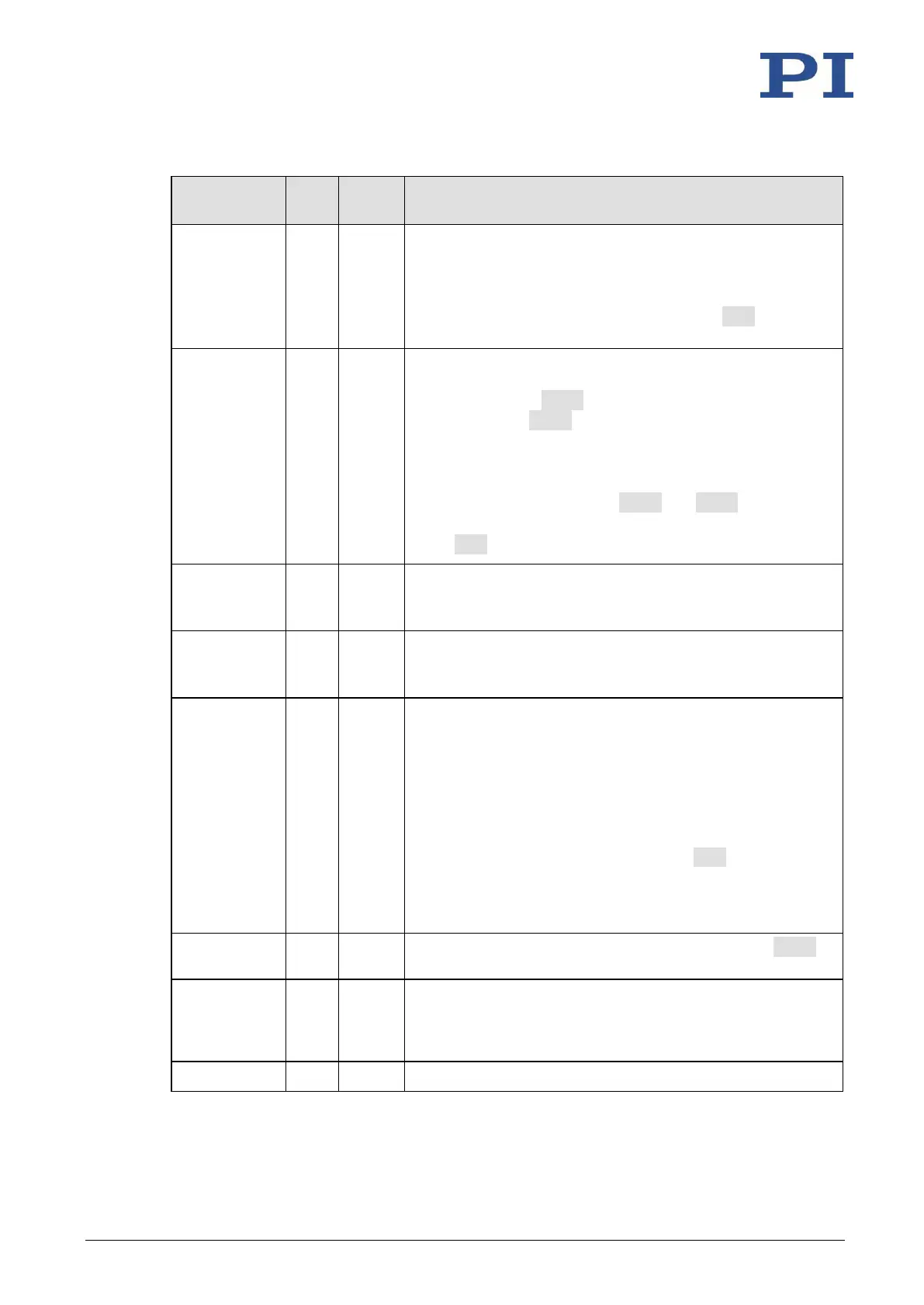
8 characters; valid characters are
1234567890ABCDEFGHIJKLMNOPQRSTUVWXYZ-_
The new axis identifier is only transferred to the volatile
memory of the C-863.12. A changed axis identifier can be
stored permanently in the C-863.12 with the WPA command
(p. 205).
The analog input lines with the identifiers 1 to 4 are the
inputs 1 to 4 of the I/O socket (p. 266). Their number is
displayed with the TAC? command and their values can be
queried with the TAV? command. Note that these lines can
also be used as digital inputs (see below).
Additional analog input lines are located at the Joystick
socket (p. 268).
These lines are not output via TAC? and TAV?.
The values of all inputs can be recorded via record option 81
of the DRC command.
1 to 4 identify digital output lines 1 to 4 of the I/O socket (p.
266).
For further information, see "Digital Output Signals" (p. 76).
1 to 4 identify digital input lines 1 to 4 of the I/O socket (p.
266), which can also be used as analog inputs (see above).
For further information, see "Digital Input Signals" (p. 83).
A joystick can be connected to the C-863.12's Joystick socket
(p. 268).
Pin 4: Commanding as axis 1 of joystick 1
Pin 6: Commanding as button 1 of joystick 1
For further information, see "Joystick Control" (p. 89).
For data recorder configuration with the DRC command, the
following data source identifiers apply:
5 = axis 1 of joystick 1
6 = button 1 of joystick 1
The C-863.12 has 4 data recorder tables (query with TNR?)
with 1024 data points per table.
The controller address can be set in the range from 1 to 16
with the DIP switches on the front panel of the C-863.12. In a
daisy chain (p. 45), each controller must have a unique
address (p. 117).
C-863.12 as an overall system