1. Needle valve - 2. Idle speed adjustment screw - 3. Max jet - 4. Accelerating pump - 5. Tapered pin -
6. Jet holder - 7. Float - 8. Chamber - 9. Starter device - 10. Vacuum valve - 11. Cover - 12. Minimum
jet.
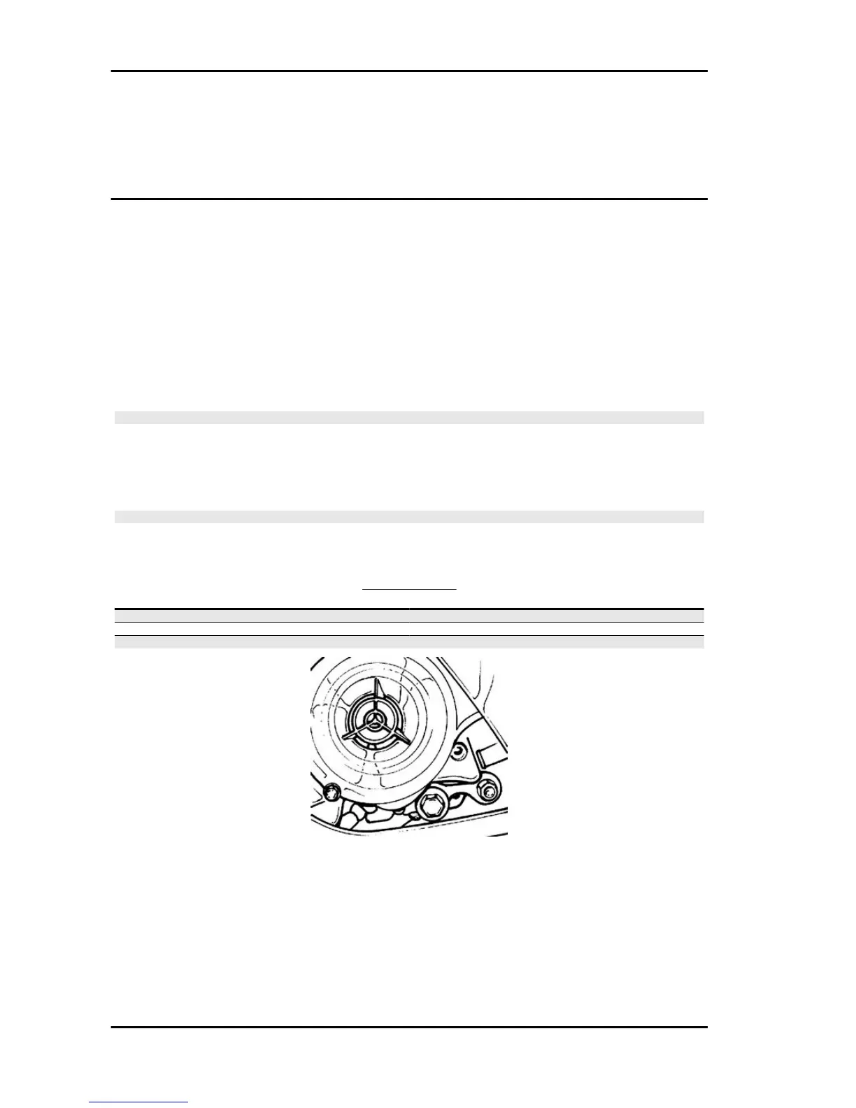
Checking the spark advance
The vehicle is provided with a variable spark advance electronic device. Two reference marks for the
timing can be found on the flywheel cover as to find out with more precision the reference mark on the
fan. To check, use a stroboscopic gun Tecnotest 130/P or similar type. Start the engine and let it run
at 1900 revs/min, act on the phase shifter to align the reference mark on the flywheel fan in between
the two reference marks on the casing; at the same time, read the spark advance value on the strobo-
scopic gun display. The value should be 10°.
Repeat the above operation with engine running at 5000-6000 revs/min, spark advance should be 26°.
CAUTION
SHOULD THE FLASH INDICATIONS BE UNSTABLE AND THE RPM INDICATION DOES NOT
CORRESPOND WITH THE TRUE ENGINE SPEED VARIATION (FOR EXAMPLE, VALUES SHOWN
ARE HALVED), INSTALL A 10 ÷ 15 KΩ RESISTIVE CABLE CONNECTED IN SERIES TO AN HV
CABLE. IF THE IRREGULAR READING CONTINUES AFTER THIS OPERATION, CHECK THE
COMPONENTS OF THE IGNITION SYSTEM.
N.B.
WHEN THE INDUCTION CLAMP READS THE SIGNAL CORRECTLY, A READING CAN BE CAR-
RIED OUT AT OVER 6000 RPM.
RPM LIMITER
Specification
Desc./Quantity
1 spark out of 7 8200 Revs/min
1 spark out of 3 8300 Revs/min
Suppression of all sparks 8500 Revs/min
Maintenance MSS Fly 50 4T
MAIN - 30
 Loading...