- Measure the coupling clearance between the sealing rings and the piston grooves using a thickness
gauge, as shown in the figure.
- If the clearances detected exceed the limits specified in the table, the piston and the piston rings should
be replaced.
PISTON
Name Description Dimensions Initials Quantity
Top piston ring 0.030 ÷ 0.065 mm 0.080 mm
Middle piston ring 0.020 ÷ 0.055 mm 0.070 mm
oil scraper 0.040 ÷ 0.160 mm 0.20 mm
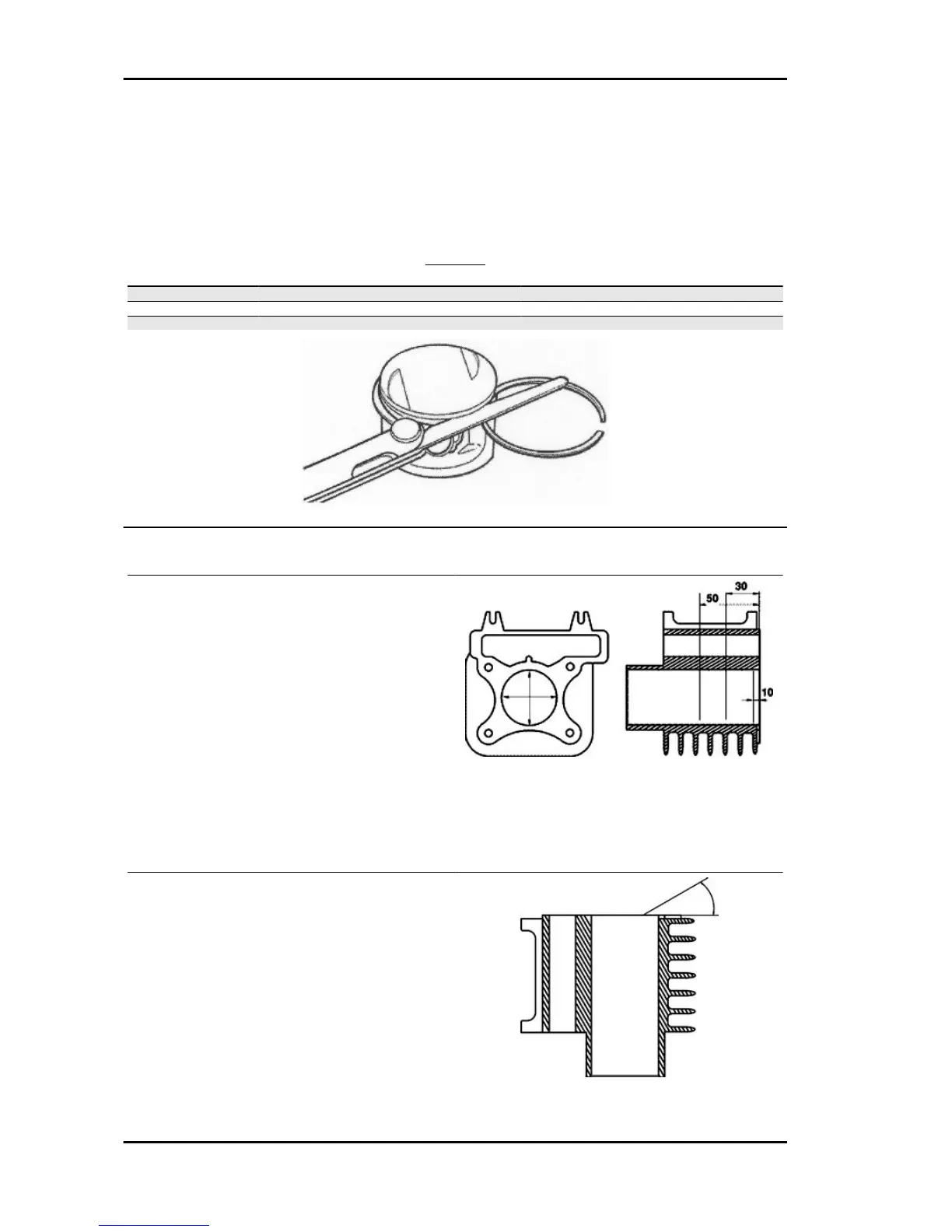
Inspecting the cylinder
- Using a bore meter, measure the inner cylinder
diameter at three different points according to the
directions shown in the figure.
- Check that the coupling surface with the head is
not worn or misshapen.
- Pistons and cylinders are classified into catego-
ries based on their diameter. The coupling is car-
ried out in pairs (A-A, B-B, C-C, D-D).
Characteristic
Maximum allowable run-out:
0.05 mm
- The cylinder rectifying operation should be car-
ried out with a surfacing that respects the original
angle. at 120° crossed.
- The cylinder surface roughness should be of
R.A.= 0.30 ÷ 0.50.
- This is indispensable for a good seating of the
sealing rings, which in turn minimises oil consump-
tion and guarantees optimum performance.
Engine MSS Fly 50 4T
ENG - 88
 Loading...