PicoQuant GmbH HydraHarp 400 Software V. 3.0.0.1
After the installation the HydraHarp software should be available in the Windows Start Menu under Programs |
PicoQuant – HydraHarp 400 v3.0 (or the folder name you chose during setup). However, before running the
software, please proceed to the hardware installation step.
3.3. Device Installation
Make sure to avoid electrostatic discharge when handling the HydraHarp system, especially when connecting
cables. Note that PMT detectors operate with high voltage that may discharge through the signal cable. Make
sure such detectors are switched off and fully discharged before connecting them.
Dependent on the model of the HydraHarp device you purchased it has a USB 2.0 or USB 3.0 interface.
Consult your PC manual as to whether and where it provides high speed USB 2.0 or super speed USB 3.0
connectors. The latter are typically blue. The minimum requirement is a USB 2.0 connection. The HydraHarp
system will NOT work through USB 1.x. All current PCs should provide at least USB 2.0 connectivity. Most
recent PCs will provide USB 3.0 out of the box. If you purchased a HydraHarp with USB 3.0 interface but the
PC has no USB 3.0 support you can install a USB 3.0 adaptor card. It is also possible to run a USB 3.0
HydraHarp device via USB 2.0 but performance will be poor. Use a proper USB 3.0 connection whenever
possible.
Always use a quality USB cable rated for the chosen USB speed. The cable length must not exceed 5 metres
(~16 ft). For best reliability we recommended to use the provided cable of 3 metres length. Note that the USB
specification does not allow cable extensions other than dedicated active extension cables or hubs. The
HydraHarp device should work flawlessly through suitable hubs. This is also a valid way of extending the
maximum cable length. After a hub, another cable of up to 5 metres is allowed. Note, however, that hubs may
lower the data throughput. For the same reasons it is recommended not to connect other bandwidth
demanding devices to the same hub.
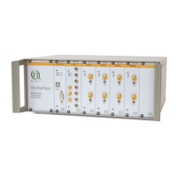
The inputs for the detector / sync signals are SMA connectors located on the front panel of the HydraHarp 400,
labelled IN and SYNC IN. In case of time resolved fluorescence experiments with a pulsed excitation source,
the sync signal must be connected to the SYNC IN input and the detector signal must be connected to an IN
port. If coincidence correlation experiments between two (or more) detector signals are to be carried out, you
need to decide whether you will be using on–board histogramming or TTTR mode. In the case of on–board
histogramming connect one detector to the SYNC input and one or more to the regular IN ports. Coincidence
timing and histogramming will always be with respect to the SYNC input. In TTTR mode it is possible to
determine the relative timing between all inputs but this requires off–line data analysis (see section 5.3).
All inputs are terminated with 50 Ω internally. Note that they need negative going input signals. Use quality
50 Ω coax leads with appropriate connectors. For interfacing to BNC connectors use standard adaptors.
Carefully screw on the SMA connectors for sync and detector until they are moderately tight. Do not use
wrenches. Connect the cable ends to the appropriate signal sources (50 Ω) in your experimental setup. The
HydraHarp 400 inputs accept negative pulses going from 0 V to max. –1 V. Both inputs should be operated
with similar pulse amplitudes to minimize crosstalk. The optimum range is –100 mV to –500 mV. Below this
range you may pick up noise, above there may be crosstalk. Most PMT and MCP detectors will require a pre–
amplifier to reach enough signal level. TTL–SPAD–detectors (e.g. Excelitas SPCM–AQR) must be connected
through a pulse inverter (PicoQuant SIA 400). Weak PMT detectors should be connected through a 20 dB high
speed pre–amplifier. MCP–PMT detectors should be connected through an amplifier with slightly higher gain.
Suitable devices are available from PicoQuant. Be sure to switch the high voltage supply of PMTs off and allow
their electrodes to discharge before connecting them. Their high voltage charge may damage the pre–amplifier.
Observe the allowed maximum ratings for the input signal levels. If you are not sure what signals your setup
delivers, use a fast oscilloscope to check the signal level and shape before connecting them to the HydraHarp.
All signals should have rise/fall times of no more than 2 ns. Slower signals may not be seen by the HydraHarp
and will certainly degrade timing accuracy.
When using the HydraHarp 400 in combination with the PDL 800–B, the sync pulses from the laser driver
should be attenuated by 10 dB to 15 dB to fall in the optimum range for smallest crosstalk.
Do not connect anything other than dedicated hardware to the other HydraHarp 400 connectors. They are
provided for hardware expansion (notably experiment control) and must not be used otherwise. See
section 8.3.2 for pin assignments. It is recommended to start instrument setup without anything connected to
the control ports.
After connecting the HydraHarp to the PC via USB for the first time, Windows should detect the device and
perform the final driver installation. Note that the software setup for the HydraHarp 400 pre–installs the driver.
Dependent on your version of Windows you may be prompted to confirm the final driver installation. Some
older windows versions verbosely warn about drivers not being validated by Microsoft. You can safely ignore
Page 17