PicoQuant GmbH HydraHarp 400 Software V. 3.0.0.1
4.6. The Trace Mapping Dialog
The HydraHarp software can measure histograms in up to 512 memory blocks. Out of these up to 8 curves can
be displayed. The Trace Mapping dialog is used to select the curves to display. It also allows to view curve
details and cleanup. You can use the Trace Map button on the Toolbar or click the curve colour indicator in the
control panel to launch the dialog.
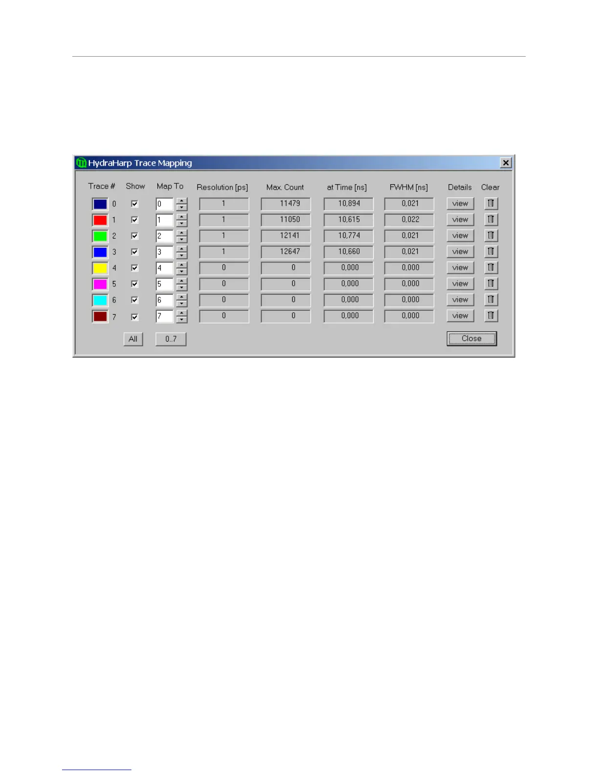
In the Trace Mapping dialog you can tick the individual boxes ‘Show’ to display a curve. Select the number of
the memory block you wish to map the individual display curve to. Choose the active memory block you wish to
use for the next measurement in the HydraHarp control panel with the Map To edit box and spin control.
The dialog also provides some statistics on each curve (central matrix of figures). Resolution is the channel
width (bin width) of the histogram in picoseconds. Next is the Max. Count, the count in the highest point of the
curve. The column At Time shows the time corresponding to the Max. Count channel. Leftmost there is the Full
Width Half Maximum (FWHM) of the curve peak (usually for IRF traces).
There are also some buttons for frequently required actions: The button 'view' can be clicked to see more
detailed curve information such as time of recording, acquisition settings and count rates. The button All can be
clicked to tick all traces as shown. The button 0..7 can be clicked to set the default mapping of trace 0..7 to
block 0..7. The Clear buttons (trash cans) can be clicked to delete the contents of individual blocks.
Note that the Trace Mapping Dialog is non–modal. This means the dialog can remain open while a
measurement is in progress, so that adjustments can be made under immediate visual control, similar to the
operation of the control panel. Note also that a measurement can be running in a block that is not mapped or
shown.
The individual axis panel items are discussed in the section 6.6. “Trace Mapping“ in the Controls and
Commands Reference.
4.7. Other Dialogs
In order to keep this manual readable, the dialogs described here are limited to the most important ones the
reader should know about before starting practical work with the software. Some more dialogs will be described
implicitly in the following sections in the context of specific measurement tasks. For information on all other
dialogs the user is kindly requested to refer to the controls and commands reference (section 6) or consult the
on–line help facility of the software. Pressing F1 in any given dialog will provide help on that dialog.
Page 24