PicoQuant GmbH HydraHarp 400 Software V. 3.0.0.1
A measurement can be stopped at any time by clicking the Stop button. The data recorded up to this point will
be in the file. When the measurement has completed, the Stop button will change to grey (disabled). Use the
Cancel button to return to the normal interactive mode. Again, this will take some time for hardware
reconfiguration.
5.3.5. External Markers
Often it is desirable to synchronize TCSPC measurements with other information or processes of complex
measurement tasks. In order to perform e.g. Fluorescence Lifetime Imaging, the spatial origin of the photons
must be recorded as well. For this purpose one needs a mechanism to assign external synchronization
information to the TCSPC data. For the special case of Fluorescence Lifetime Imaging, conventional systems
use large arrays of on–board memory and switch to new blocks of memory upon arrival of e.g. a pixel clock
pulse. To accommodate the large amount of data generated due to the 3–dimensional matrix of pixel co–
ordinates and lifetime histogram channels causes serious problems. Even with modern memory chips, this
approach is limited in image size and / or number. In addition, it is expensive, and implies loss of information
about the individual photon arrival times. To solve the problem much more elegantly, the TTTR data stream
generated by the HydraHarp can contain markers for synchronization information derived from an imaging
device, e.g. a scan controller. For this purpose the front panel of the HydraHarp SYNC module HSR 110
provides four TTL inputs for synchronization signals (M1..M4).
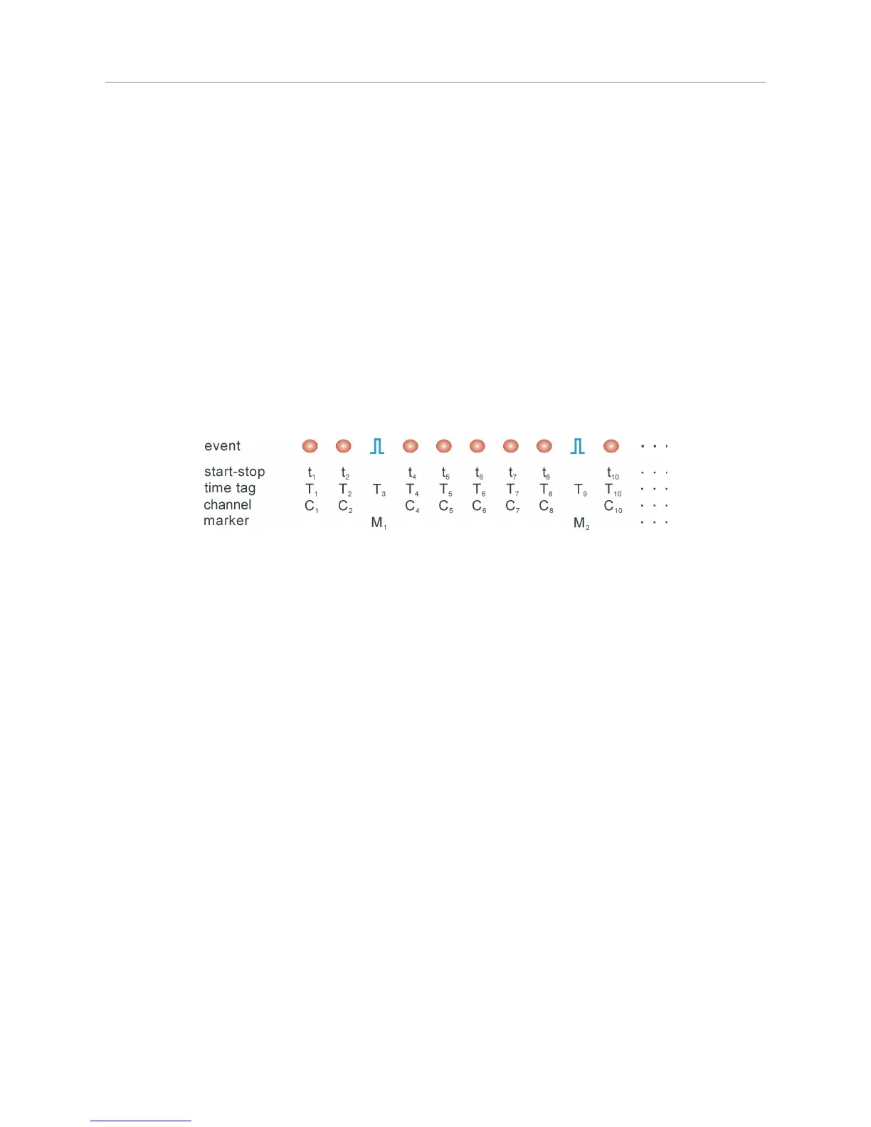
The figure below illustrates how the external marker signals are recorded in the data stream.
Bullets denote a photon, blue pulses denote a marker signal. The external markers are treated almost as if they
were regular photon event records. A special channel code allows to distinguish true photon records from the
marker records. Software reading the TTTR file can thereby filter out the markers, e.g. for line and frame clock
in imaging applications. This makes it possible to reconstruct the 2D or 3D image from the stream of TTTR
records, since the relevant XYZ position of e.g. a scanner can be determined during the data analysis. The
data generated is nearly free of redundancy and can therefore be transfered in real–time. The image size is
unlimited both in XYZ and in count depth. Since there are up to four such synchronisation signals, all imaging
applications can be implemented and even other experiment control signals can be recorded. This marker
scheme is a very special innovative feature of the PicoQuant TCSPC electronics. It is worth noting that this
technology enabled PicoQuant GmbH to develop the leading edge MicroTime 200 Fluorescence Lifetime
Microscope.
The TTL compatible inputs accept the synchronization signals that will be recorded as markers. The active
edges of these signals can be chosen in the general settings dialog (available through the Toolbar). Both high
and low state must be at least 50 ns long. The period may therefore (in principle) be as short as 100 ns but
data bus throughput constraints will apply. Each marker creates an additional TTTR record, so that one must
ensure not to swamp the data stream with too many marker records. Markers also take precedence over
photon records, so that excess marker traffic can suppress photon records. In fast imaging applications it is
therefore recommended not to use a pixel clock but a line clock only. Since each photon has a time tag, it is
usually not necessary to use an additional pixel clock. The accuracy of marker timing is on the order of 50 ns.
For each channel there is another TTL input that can be used to externally enable / disable the recording of
incoming counts (see section 8.3.2). Counting is enabled when this input is held high (or left open). Pulling it
low disables counting. This mechanism can be used to blank out periods where e.g. an external scanner is
moving to the next position. The count enable signal is also active in interactive mode. It may be used to
synchronize the start of acquisition with external events.
5.3.6. Using TTTR Mode Data Files
For diagnostic purposes you may re–load a T3 mode file into the HydraHarp software. The limitation is that you
will only be able to form a histogram over the start–stop times in your T3 mode data. The time–tag information
will not be used here. The HydraHarp software will recognize that you are loading a T3 mode file and how
many records there are contained in it. It will then prompt you for a range to use for histogramming. The
Page 33