PicoQuant GmbH HydraHarp 400 Software V. 3.0.0.1
8.3.2. Connectors
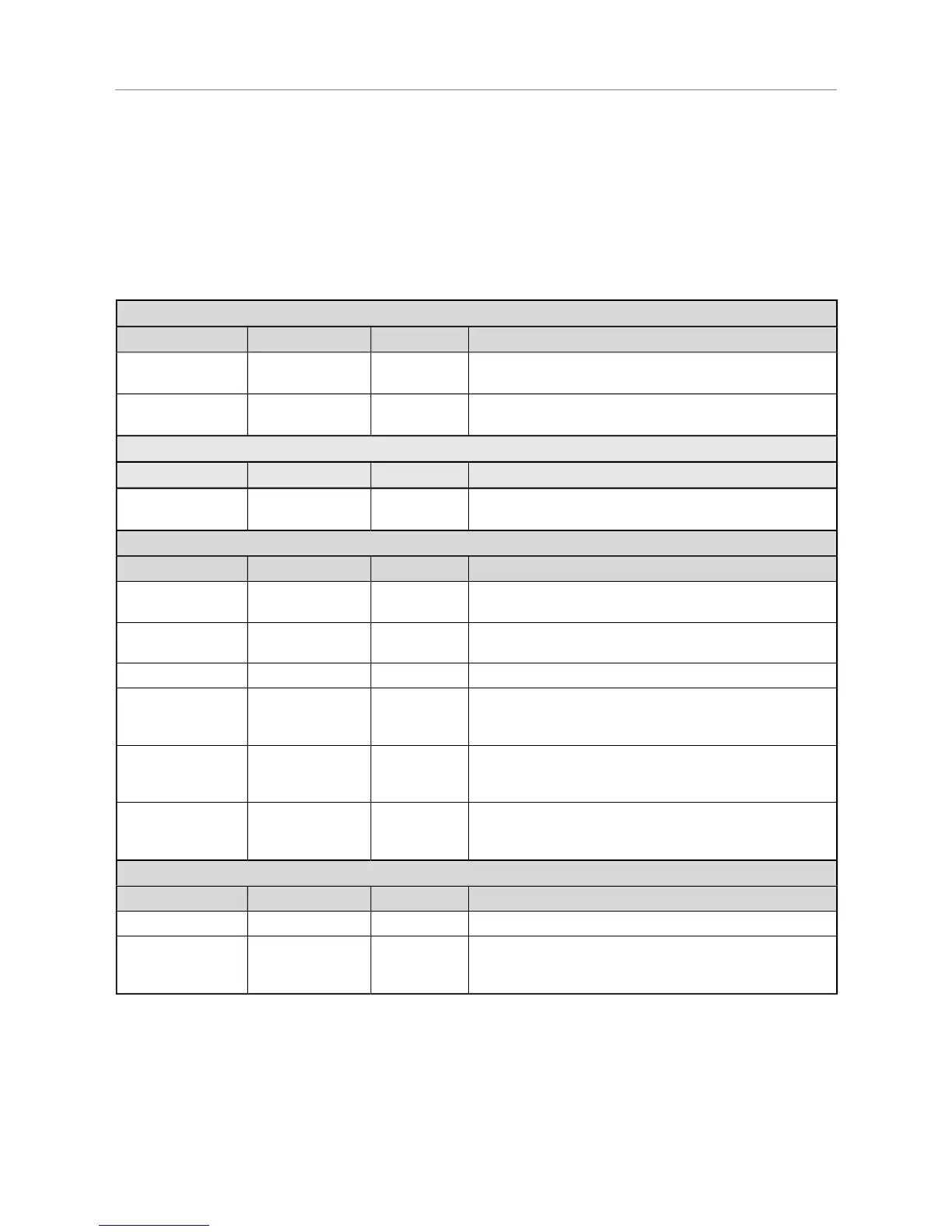
Apart from the SMA connectors for the input signals the HydraHarp 400 provides several connectors for other
purposes such as experiment control. The following table lists their function and signal types, sorted by the
module they belong to. For details on the signal specifications (voltages, pulse widths etc.) see section 8.3.1.
All SMA connectors are designed for 50 Ohms coaxial cable connections and are terminated accordingly. All
Lemo connectors are for high impedance TTL signals and not terminated. In case of TTL outputs they must
never be connected to loads with 50 Ohms termination.
HDU 404 (CONTROL)
Connector Label Connector Type Signal Type Function
USB 2.0 USB 2.0 Type B
receptacle
USB 2.0 host communication
CAN Sub–D 9 pin
male
CAN Bus control of external devices (proprietary)
HDU 504 (CONTROL)
Connector Label Connector Type Signal Type Function
USB 3.0 USB 3.0 Type B
receptacle
USB 3.0 host communication
HSR 110 (SYNC)
Connector Label Connector Type Signal Type Function
REF IN SMA female 10 MHz clock
in
external reference clock, e.g. from a frequency normal
or atomic clock, or from another HydraHarp 400
REF OUT SMA female 10 MHz clock
out
reference clock output e.g. for another HydraHarp 400
SYNC IN SMA female NIM in timing signal from sync source (typically a laser)
M1 ... M4 NIM-CAMAC
receptacle Lemo
ERN.00.250**
TTL in external markers for external device synchronization,
e.g. line and frame in image scanning
(select active edge and enabling via software)
C1 ... C2 NIM-CAMAC
receptacle Lemo
ERN.00.250**
TTL in experiment control (requires dedicated software)
A NIM-CAMAC
receptacle Lemo
ERN.00.250**
TTL out
(active low)
'active' signal for use by external hardware
(must not be loaded in excess of 10 mA)
TDC 210 (TIMING)
Connector Label Connector Type Signal Type Function
IN SMA female NIM in timing signal input (typically from a photon detector)*
ENA NIM-CAMAC
receptacle Lemo
ERN.00.250**
TTL in count enabling of the corresponding input*
(high or open = enabled, low = disabled)
*Note: The HydraHarp software enumerates the physical input channels as logical input channels 1 to N, where N depends on the number
of installed TDC modules. The mapping of physical to logical channels is obtained by counting as follows: start form the leftmost TDC
module and count top to bottom within each TDC module. At the time of factory assembly this mapping will be marked by plastic labels at
each IN connector.
** Suitable plugs from the Lemo catalog are FFA.00.250.xxx. Alternatively the BNC adaptor ABF.00.250.CTA can be used.
Page 68