MAINTENANCE
6-14 / Electrical
© 2020 Pierce Manufacturing Inc. All Rights Reserved.
Electrical
6-14. Command Zone™ System
6-14.1 Overview
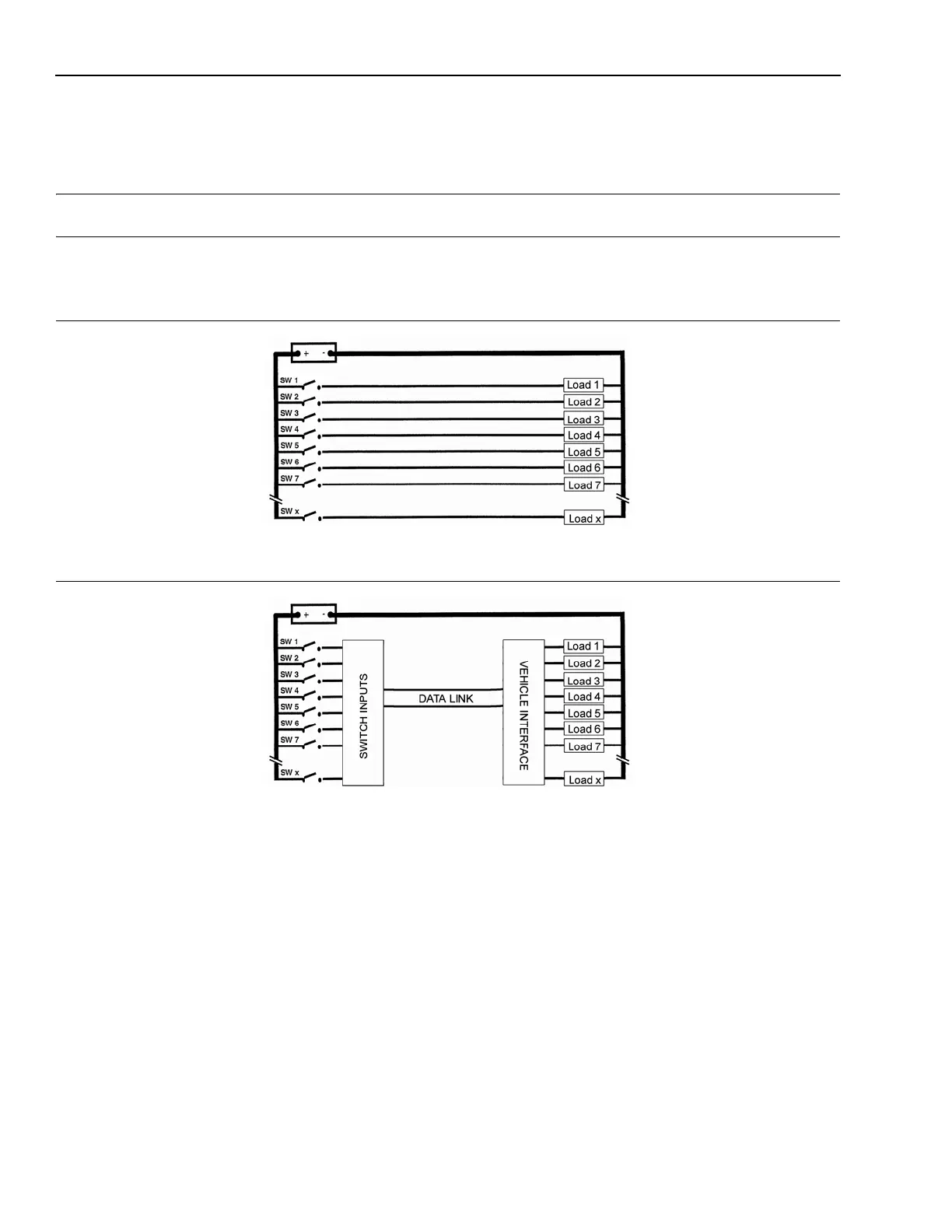
Figure 6-3: Traditional Electrical System
POM0111
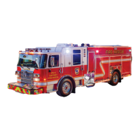
Figure 6-4: Pierce Command Zone™ Multiplex System
POM0112
The multiplex electrical system is different from most traditional electrical systems. Traditional truck electrical
systems (Figure 6-3) use individual wires, switches, and components to operate discrete systems. This usually
results in the use of large power distribution boxes and large main wiring harnesses. Many electro-mechanical relays
are also needed to perform operational interlock functions.
The Pierce Command Zone™ multiplex system (Figure 6-4) uses a single, three-wire, wire harness or data link to
connect switches and controls (inputs) to system loads and devices (outputs). The use of this single data link vastly
reduces the amount of wiring used within an electrical system. System inputs and outputs are connected to modules
located along the single data link.
The input from several switches is combined together in an input/output or input module which connects to the data
link. Similarly, many outputs are connected together in an output module or power module which also connects to
the data link. In most cases the power module controls the higher amperage load of the components. A control
module is used to interpret switch functions, facilitate communications with other multiplex devices, and perform
desired interlock functions.
Additional information on the Command Zone™ system can be found in the Pierce Service Manual, group
0950-P-009, Command Zone™ Advanced Electronics.