EasyManuals Logo

Pilz PNOZ m1p User Manual

Pilz PNOZ m1p
43 pages
To Next Page IconTo Next Page
To Previous Page IconTo Previous Page
Page #41 background imageLoading...
Page #41 background image
Supplementary data
Operating Manual PNOZ m1p (ETH)
20878-EN-16
41
Number of cycles x 1000
Switching current (A)
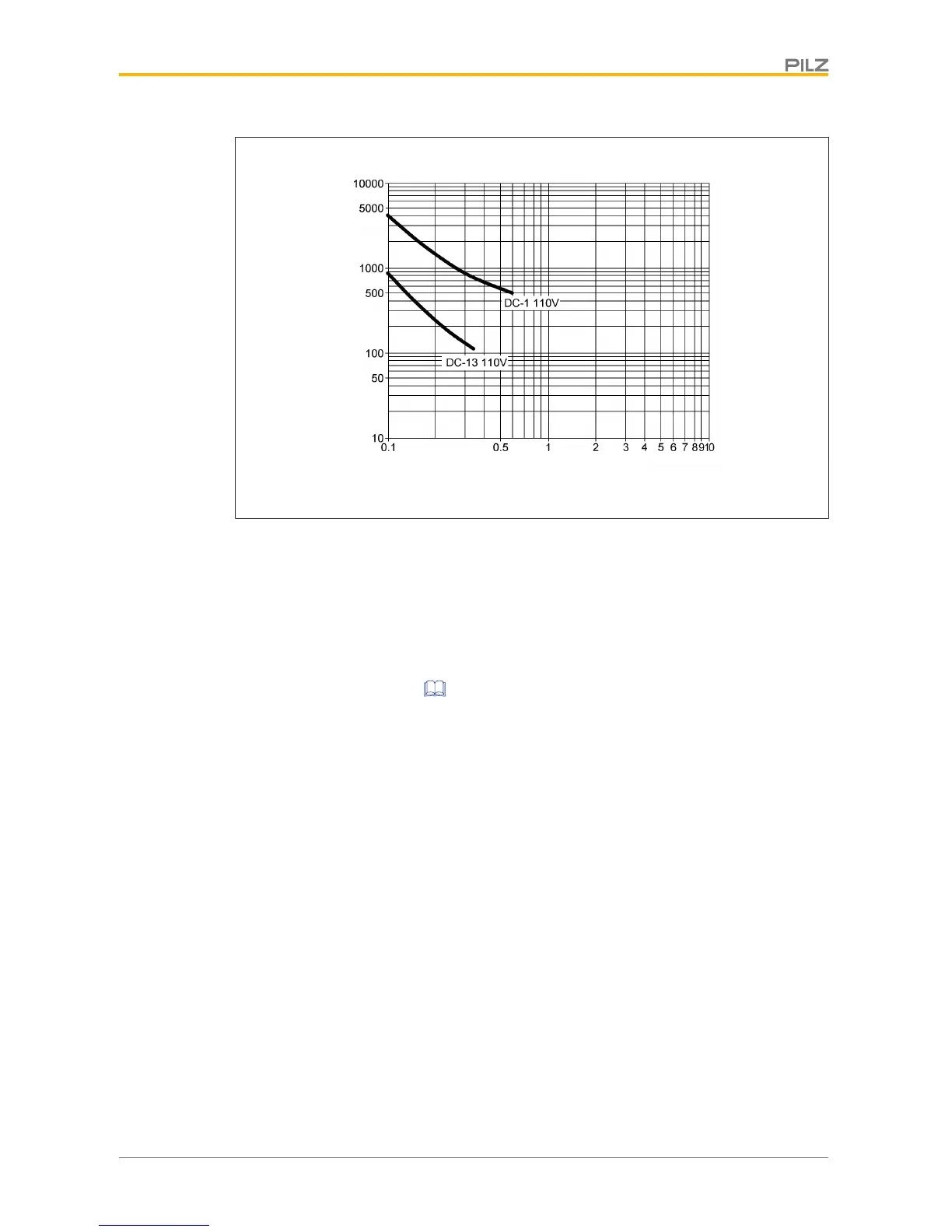
Fig.: Service life graphs at 110 VDC
Example
} Inductive load: 0.2 A
} Utilisation category: AC15
} Contact service life: 1 000 000 cycles
Provided the application to be implemented requires fewer than 1 000 000 cycles, the PFH
value (see Technical details [ 30]) can be used in the calculation.
To increase the service life, sufficient spark suppression must be provided on all relay con-
tacts. With capacitive loads, any power surges that occur must be noted. With DC contact-
ors, use flywheel diodes for spark suppression.
We recommend you use semiconductor outputs to switch 24 VDC loads.

Other manuals for Pilz PNOZ m1p

Questions and Answers:

Question and Answer IconNeed help?

Do you have a question about the Pilz PNOZ m1p and is the answer not in the manual?

Pilz PNOZ m1p Specifications

General IconGeneral
Supply Voltage24 V DC
Number of Safe Inputs20
Number of Safe Outputs8
Number of Standard Outputs4
Protection TypeIP20
Expansion ModulesYes
Safety CategoryEN ISO 13849-1: PL e
Communication InterfaceEthernet
Operating Temperature Range-20°C to +60°C
Dimensions (W x H x D)45 mm x 121 mm
StandardsEN ISO 13849-1, EN 62061, EN 61508

Related product manuals