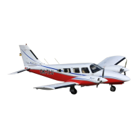
LANCE II SERVICE MANUAL
SECTION
VII
LANDING GEAR AND BRAKE SYSTEM
7-1. INTRODUCTION. In this section are instructions for the overhaul, inspection and
adjustment of the various components of the landing gear and brake system. Also are
adjustments for the electrical limit, safety and warning switches. This section though does not
cover the hydraulic function of the landing gear, except brakes, and this information may be
found in the hydraulic section listed as Section VI.
7-2. DESCRIPTION. The Lance II is equipped with a retractable tricycle air-oil strut type
landing gear which is hydraulically operated by an electrically powered reversible pump. A
selector handle
on the instrument panel to the left of
the control quadrant is used to select gear
UP or DOWN positions.
Gear positions are indicated by three green lights located above the selector lever for gear
down and locked, and a red light located at the top of the instrument panel for gear unsafe
positions. There is no light to indicate
the gear has fully retracted other than
all lights are out.
As the landing gear swings to the down position and each downlock hook moves into its locked
position, a switch at each hook actuates to the switch normally closed (NC) circuit to indicate
by
a green light that the
individual gear
is safely down and locked.
The activation
of all three
downlock switches
will also shut the hydraulic pump
off. As the instrument lights are turned
on, the green lights will dim. When
the gear begins to retract and the
downlock hook
disengages, the down limit switch actuates to the NC circuit and in series with the NC circuit of
the up limit switch allows the gear unsafe light to come on. The gear unsafe light will remain on
until the gear
is up and all up limit switches are actuated
to their normally open (NO) circuit.
The red gear
unsafe light also operates simultaneously
with the warning horn, and
in
conjunction they have a twofold purpose.
Their primary purpose is to
give warning when
power is reduced below approximately
14 inches of manifold pressure and the
landing gear has
not reached the down
and locked position. This circuit is
controlled by the three paralleling
down limit switches connected
in series with a throttle switch (Switch
"A") located in the
control quadrant.
The secondary function of the
warning light and horn is to give warning
when the gear selector handle is up and while the airplane is on the ground or airspeed is below
that required to close the hydraulic
valve and the pump switch of
the backup gear extender
unit. When
the airplane is setting on the ground, the
warning circuit is controlled through
the
NO side of the safety switch (squat
switch) located on the left gear and the
up position of the
selector lever. Should
the airplane be raised from the ground,
such as in flight, far enough to
move
the safety switch to its NC position,
then current is directed in series through
the
hydraulic pressure switch, the pump switch (providing airspeed has actuated the switch to its
NO position),
throttle
switch on
PA-32RT-300
only (Switch
"B") and
the up positioned
selector lever. Throttle switch "B" on PA-32RT-300 only is located forward of the instrument
panel
directly below the arm of the throttle
lever. The up limit, safety, throttle, pressure
and
selector
switch, and pump
solenoids are all
protected by the landing
gear control
and warning
circuit protector. (Refer to Section XI for electrical schematic.)
Revised:
10/3/80
LANDING
GEAR
AND BRAKE
SYSTEM
1J5
 Loading...


