1.
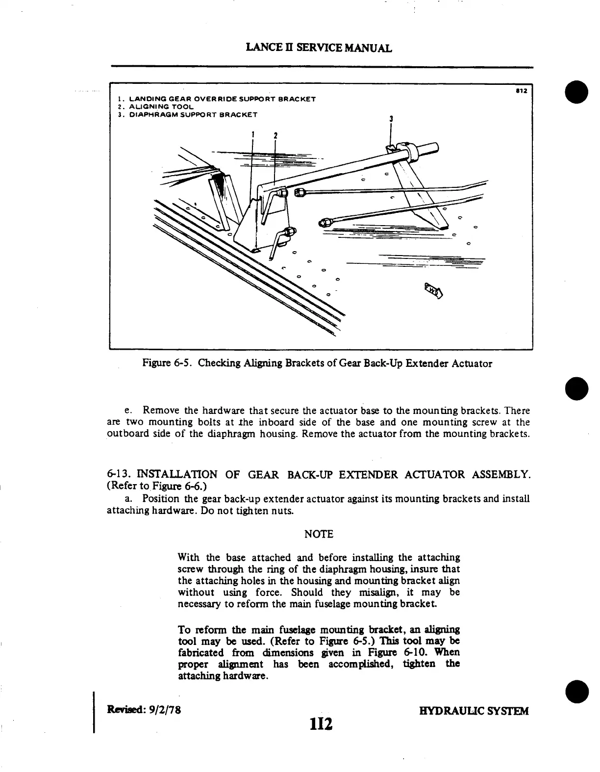
LANDING GEAR OVERRIDE
SUPPORT BRACKET
2. ALIGNING TOOL
3. DIAPHRAGM SUPPORT BRACKET
LANCE
II
SERVICE
MANUAL
Figure
6-5. Checking Aligning Brackets
of Gear Back-Up Extender
Actuator
e. Remove the hardware
that secure the actuator base
to the mounting brackets. There
are two mounting
bolts at the inboard
side of the base
and one mounting
screw at the
outboard side of the diaphragm housing.
Remove the actuator from the
mounting brackets.
6-13.
INSTALLATION
OF GEAR BACK-UP
EXTENDER
ACTUATOR
ASSEMBLY.
(Refer to Figure 6-6.)
a. Position the gear back-up extender actuator against its mounting brackets and install
attaching
hardware. Do not
tighten nuts.
NOTE
With the base
attached and before installing
the attaching
screw through the ring of the diaphragm housing, insure that
the attaching holes in the housing and mounting bracket align
without
using force. Should
they misalign, it may
be
necessary to reform the main fuselage mounting bracket.
To reform the main fuselage
mounting bracket,
an aligning
tool may be used. (Refer to Figure 6-5.) This tool may be
fabricated from dimensions given in Figure 6-10. When
proper alignment has been accomplished, tighten the
attaching hardware.
Revised:
9/2/78
0
HYDRAULIC
SYSTEM
112