EasyManuals Logo

Piper Lance II User Manual

Piper Lance II
568 pages
To Next Page IconTo Next Page
To Previous Page IconTo Previous Page
Page #487 background imageLoading...
Page #487 background image
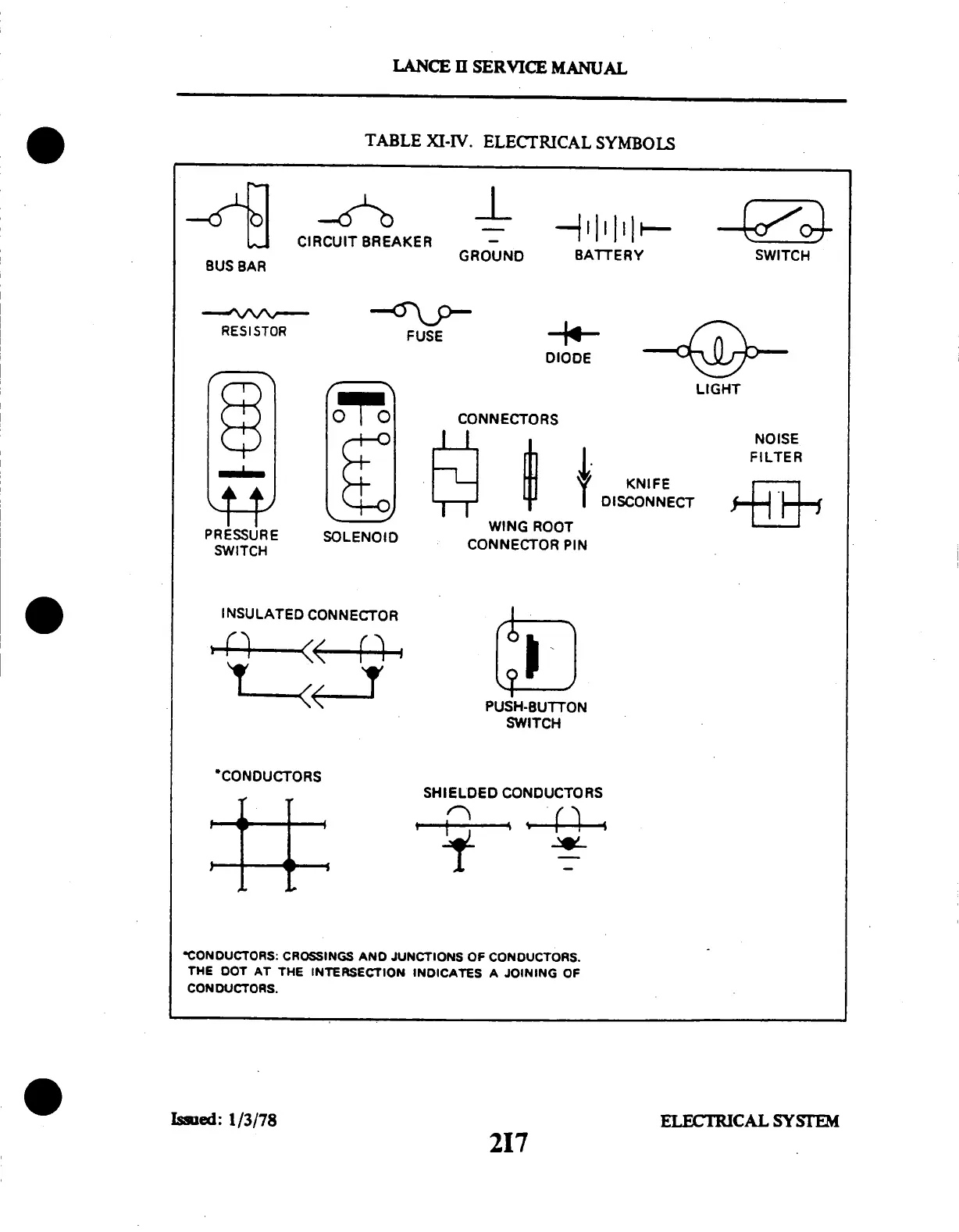
RESISTOR
PRESSURE
SWITCH
INSULATED
CONNECTOR
LANCE
I
SERVICE
MANUAL
TABLE
XI-IV.
ELECTRICAL
SYMBOLS
BUS
BAR
CIRCUIT
BREAKER
GROUND
BATTERY
SWITCH
FUSE
DIODE
SOLENOID
CONNECTORS
WING
ROOT
CONNECTOR
PIN
NOISE
FILTER
KNIFE
DISCONNECT
SWITCH
*CONDUCTORS
SHIELDED
CONDUCTORS
*CONDUCTORS:
CROSSINGS
AND
JUNCTIONS
OF CONDUCTORS.
THE
DOT
AT
THE
INTERSECTION
INDICATES
A JOINING
OF
CONDUCTORS.
Issed:
1/3/78
ELECTRICAL
SYSTEM
217

Table of Contents

Questions and Answers:

Question and Answer IconNeed help?

Do you have a question about the Piper Lance II and is the answer not in the manual?

Piper Lance II Specifications

General IconGeneral
ManufacturerPiper Aircraft
Max Takeoff Weight3, 600 lb (1, 633 kg)
Crew1
Horsepower300 hp
Seats6
Length27 ft 7 in (8.41 m)
Capacity5 passengers

Related product manuals