LANCE II SERVICE MANUAL
10-22. TROUBLESHOOTING.
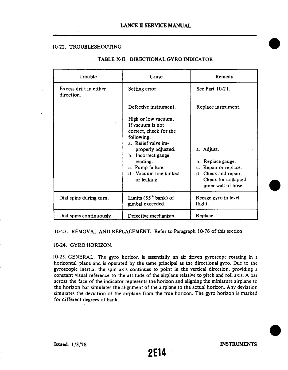
TABLE X-II. DIRECTIONAL GYRO INDICATOR
Trouble Cause Remedy
Excess drift in either
direction.
Setting
error.
See Part 10-21.
Defective instrument.
High or
low vacuum.
If
vacuum
is not
correct,
check for
the
following:
a. Relief
valve
im-
properly
adjusted.
b. Incorrect
gauge
reading.
c. Pump
failure.
d. Vacuum line kinked
or leaking.
Replace
instrument.
a. Adjust.
b. Replace gauge.
c. Repair or replace.
d. Check and repair.
Check for collapsed
inner wall of hose.
Dial spins during turn.
Limits (55 bank) of
gimbal
exceeded.
Recage
gyro in level
flight.
Dial spins continuously.
Defective mechanism.
Replace.
10-23. REMOVAL AND REPLACEMENT.
Refer to Paragraph 10-76
of this section.
10-24. GYRO HORIZON.
10-25. GENERAL. The gyro horizon is essentially an air driven gyroscope rotating in a
horizontal plane and is operated by the same principal as the directional gyro. Due to the
gyroscopic inertia, the spin axis continues to point in the vertical direction, providing a
constant visual reference to the attitude of the airplane relative to pitch and roll axis. A bar
across the face of the indicator represents the horizon and aligning the miniature airplane to
the horizon
bar simulates the alignment of the airplane
to the actual horizon. Any deviation
simulates the deviation of
the airplane from the true horizon. The
gyro horizon is marked
for different
degrees
of bank.
Issued:
1/3/78
INSTRUMENTS
2E14